background image

6.5 Position Examinee

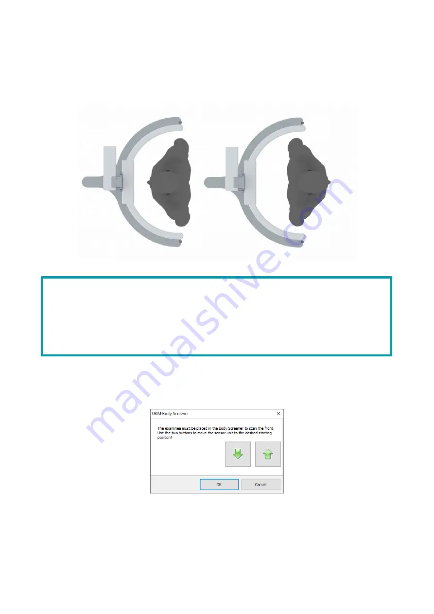
The person to be measured is placed in the middle of the circle. The feet and shoulders should be
on the axis of the ends of the semicircular truss, the feet parallel to each other (comfortably
spaced). The arms hang relaxed about 10 cm to the left and right of the body.

Depending on the examinee's body height, the sensor unit must be moved to the desired starting
position. This is accomplished by clicking the arrow buttons in the dialog window (Figure 22) with
the left mouse key.

The desired starting position of the sensor unit should be at the height of the top of the examinee's
head. If the upper line of the head is exactly between two potential starting positions, the higher
position must be selected. After confirming the start position with  

OK

, the body measurement

begins.

26

The measurement can be performed in light, comfortable clothing.

If possible, metallic/magnetic objects such as mobile phones, wristwatches, belts, 

etc. should be removed before the measurement. 

Measurements with pacemakers, implants etc. are possible.

Figure 21: Position examinee in the Body Screener

Figure 22: Set sensor unit start position

Summary of Contents for BODY SCREENER

Page 1: ...USER MANUAL...

Page 2: ...responsible for compliance with applicable copyright laws Notwithstanding the copyright of OKM GmbH the user is only permitted to duplicate and or provide this manual and or parts of it with the expr...

Page 3: ...and with Extension Element 9 3 2 3 Assembly of the Sensor Unit 10 3 3 Power On Power Off 10 4 Installation of the Body Screener Software 11 4 1 Establishing a Data Connection with the PC 13 4 1 1 Conn...

Page 4: ...ance 29 7 1 Cleaning the Body Screener 29 7 2 Maintenance of the Body Screener 29 8 Body Screener Floor Mat 30 8 1 Floor Mat as Positioning Support 30 8 2 Cleaning and Care of the Floor Mat 30 8 2 1 P...

Page 5: ...en of the software application 16 Figure 13 Comparison of window arrangements 17 Figure 14 Status bar with selection of the color representation 18 Figure 15 Set options for zero adjustment and measur...

Page 6: ...120 x 225 x 100 cm Dimensions BxHxT Sensor unit 105 x 13 x 65 cm Weight Stand with base ca 40 kg Weight Sensor unit ca 4 kg Input voltage 19 V 10 max 3 19 A use OKM Power Supply only Operating tempera...

Page 7: ...recommended before each measurement in order to avoid incorrect representations of the measurement results in case of incorrect calibration half of the person may be shown in blue Persons standing or...

Page 8: ...the electronics sensor unit via WLAN or USB cable depending on the model to the included PC software Further information on establishing a connection and operation are found in section 4 1 Establishi...

Page 9: ...magnetic resonance imaging loudspeakers motors chargers and charging stations 3 2 2 Assembly of the Stand with Extension Element 1 Place extension element onto the lower stand 2 Join the fittings toge...

Page 10: ...nnect the motor cable with the sensor unit 4 Plug the power cable into the Body ScreenerTM Then plug the connector into the wall socket 3 3 Power On Power Off By connecting the power supply the Body S...

Page 11: ...After starting the setup process the User Account Control of Windows might appear with the following message Do you want to allow this app from an unknown publisher to make changes to your device Conf...

Page 12: ...keep the suggested settings We recommend creating the desktop shortcut to easily launch the Body Screener program This option is already preselected during installation 12 Figure 3 Select installation...

Page 13: ...ccessful WiFi connection you have to enter the 8 digit password that is included in your Body ScreenerTM package After the connection has been established you will also see a corresponding message wit...

Page 14: ...in figure 8 Click the item Update driver to start installing the proper USB drivers From the subsequent dialog figure 9 left you choose Browse my computer for driver software In the next dialog figur...

Page 15: ...successfully the new entry OKM Quick Link appears in Windows Device Manager right below category Universal Serial Bus controllers The installation of the USB drivers is completed now You may close the...

Page 16: ...ionalities which will be explained in the next sections 5 1 1 File New measurement Starts a new body measurement see section 6 Perform a Body Measurement on page 24 Open Opens a previously saved measu...

Page 17: ...windows from top to down Arrange horizontally Arrange windows from left to right Minimize all All windows will be minimized Close Closes the current window overlapping arranged horizontally arranged...

Page 18: ...y ScreenerTM Select between WiFi or USB see section 6 Perform a Body Measurement on page 24 Start new measurement Starts a new body measurement including zero adjustment see section 6 Perform a Body M...

Page 19: ...sentation of the examinee in left view Alternatively the body can be rotated by 360 keep left mouse key pressed and move mouse Scale down Zoom out gradually adjustable alternatively by mouse wheel Sca...

Page 20: ...parency The schematic representation of the body can be changed step by step using the two buttons The transparency allows a better inside view of the body and its internal organs in order to locate p...

Page 21: ...Nervous system schematic representation of the brain and nervous system Cardiovascular system schematic representation of the heart and blood circulation system Respiratory system schematic representa...

Page 22: ...value determines how many minor deviations are permitted during the measuring process Threshold measuring process This value sets the lower limit of the IJD Sensor that must not be undercut during th...

Page 23: ...firm your selection with OK After establishing the data connection successfully the status bar should indicate Connected you have to click the button to start a new measurement The measuring process t...

Page 24: ...4 Perform Calibration Zero Adjustment Before the actual measurement takes place a so called zero adjustment is performed During this process the current magnetic field of the surrounding environment i...

Page 25: ...ues Cancel Cancel the current measurement process The zero adjustment is performed without the presence of any examinee Depending on the selected resolution this reference measurement takes approx 8 t...

Page 26: ...gure 22 with the left mouse key The desired starting position of the sensor unit should be at the height of the top of the examinee s head If the upper line of the head is exactly between two potentia...

Page 27: ...e completion of the first measurement At the end of the measurement of the front side a message appears on the screen indicating that the examinee must turn 180 for the second measurement back side Cl...

Page 28: ...as optimal energy consumption normal healthy body areas increased energy consumption potentially affected body areas maximum energy consumption inflamed affected body areas The visualization of the me...

Page 29: ...e Body Screener Maintenance should be carried out by qualified and trained personnel only The sensor unit can be easily dismantled for this purpose Please refer to the notes in section 3 2 3 Assembly...

Page 30: ...nd as pictured in figure 25 The feet of the examinee are placed on the gray ovals The center of the examinee s body should be approximately at the ends of the semicircular truss 8 2 Cleaning and Care...

Page 31: ...at least every 4 weeks to avoid discoloration Drying possible at 65 to 80 C for approx 7 minutes after cooling down approx 30 to 40 C dry again for 7 minutes Storage do not fold store flat and dry at...

Page 32: ...e device close to magnetic fields or iron carriers Ensure that the device and the floor mat are aligned correctly Do not place any objects close to the sensor unit Do not use extension cords or cable...

Reviews: