background image

Oki  Data  CONFIDENTIAL

43641601TH  Rev.1 

53 / 

Blink 1:  2 s cycle.  Blink 2:  500 ms cycle.  Blink 3:  120 ms cycle.

Table 5-1 (4 of 4)

Displayed Status

Printer's LED Light

Description/Corrective Action

Status

Detail

Illegal file name

Invalid file name.

Varies

Varies

Blink 1 Invalid file name. (B2400n Only

Root directory  
deleting error

Root directory 
cannot be deleted.

Varies

Varies

Blink 1 Root directory cannot be deleted. (B2400n Only

Directory operating 
error

Operation has 
been sent to the 
file handling the 
directory.

Varies

Varies

Blink 1 Operation  has  been  sent  to  the  file  handling  the 

directory. (B2400n Only

File operating error

Operation has 
been sent to the 
directory handling 
the file.

Varies

Varies

Blink 1 Operation has been sent to the directory handling 

the file. (B2400n Only

Different volume

The volume is dif-
ferent.

Varies

Varies

Blink 1 The volume is different. (B2400n Only

Read only

Read only

Varies

Varies

Blink 1 Read only (B2400n Only

Root directory full

Root directory full.

Varies

Varies

Blink 1 Root directory full. (B2400n Only

Error deleting  
directory

The directory is 
not empty.

Varies

Varies

Blink 1 The directory is not empty. (B2400n Only

Disk error

Disk error

Varies

Varies

Blink 1 Disk error (B2400n Only

No label

No label

Varies

Varies

Blink 1 No label (B2400n Only

Invalid parameter

Invalid parameter

Varies

Varies

Blink 1 Invalid parameter (B2400n Only

No continuous 
space

There is no con-
tinuous space.

Varies

Varies

Blink 1 There is no continuous space. (B2400n Only

Error changing 
directory

Root direc-
tory cannot be 
changed.

Varies

Varies

Blink 1 Root directory cannot be changed. (B2400n Only

File descriptor error The file descriptor 

is obsolete.

Varies

Varies

Blink 1 The file descriptor is obsolete. (B2400n Only

Deleted

 It has been de-
leted.

Varies

Varies

Blink 1  It has been deleted. (B2400n Only

Block device error

There is no block 
device.

Varies

Varies

Blink 1 There is no block device. (B2400n Only

Seek error

Seek error.

Varies

Varies

Blink 1 Seek error. (B2400n Only

Internal error

Internal error.

Varies

Varies

Blink 1 Internal error. (B2400n Only

Write only

Write only

Varies

Varies

Blink 1 Write only (B2400n Only

File is write  
protected

You cannot write 
to a protected file.

Varies

Varies

Blink 1 You cannot write to a protected file. (B2400n Only

Summary of Contents for B2200

Page 1: ...Oki Data CONFIDENTIAL B2200 B2400 Maintenance Manual 151107A...

Page 2: ...acturers and referred to in this guide will not affect the applicability of the information in it Mention of software products manufactured by other companies does not necessarily constitute endorseme...

Page 3: ...e note that you should refer to the Printer Handbook for the handling and operating methods of the equipment Note All or any part of contents is not allowed to be reproduced without permission from th...

Page 4: ...3 3 LED Head 20 2 3 4 Cover Assy Top 21 2 3 5 High voltage power supply 1 Sensor board 22 2 3 6 Flame base unit 23 2 3 7 Plate Side M and Gear 27 2 3 8 Main motor 28 2 3 9 Hopping roller Assy 29 2 3 1...

Page 5: ...age Problems 49 5 4 Preparation for Troubleshooting 49 5 5 Troubleshooting Flow 50 5 5 1 Status Message Problem Tables 50 5 5 2 Message Troubleshooting 60 5 5 3 Image Troubleshooting 67 6 WIRING DIAGR...

Page 6: ...Figure 1 1 Operator panel Electrophotographic Processing Unit LED 4 SW 1 Main motor Paper cassette Image drum cartridge Paper feeding mechanism Hopping clutch LED Head Fuser unit Halogen lamp High vol...

Page 7: ...ts of the following hardware components Electrophotographic Processor Paper Feeder Controller Operator Panel Power Supply Unit The printer unit configuration is shown in Figure 1 2 Figure 1 2 High vol...

Page 8: ...method Warm up time About 25 seconds 25 77 F Type Weight Thickness Size Paper feeding Remarks Tray 1 Manual Plain paper Heavy paper Ream weight 55 75kg Ream weight 76 90kg A4 210x297 A5 148x210 A6 10...

Page 9: ...shipping 20 122 29 50 With drum and toner Note Only for packed unit 1 Storage conditions specified above apply to printers packed in cardboard boxes for shipping 2 Temperature and humidity must be in...

Page 10: ...de Silence Back ground level 14 Consumables Toner cartridge About 2 000 pages A4 ISO IEC 19752 printing pattern continuous printing Except the first toner cartridge that is set in the new drum cartrid...

Page 11: ...ctric shock and especially a caution marking is put on the low voltage power supply A heatsink and a core of transformer involve the risk of electric shock Test before touching Even after fuse opening...

Page 12: ...Connect the AC cord and interface cable to the printer ii Connect the AC inlet plug to the AC receptacle iii Turn on l the power switch of the printer 2 Do not disassemble the printer as long as it i...

Page 13: ...boards assemblies and units are listed in Table 2 1 Table 2 1 Service Tools No Service Tools Q ty Application Remarks 1 No 1 100 Philips screwdriver 1 2 2 5mm screws 2 No 2 100 Philips screwdriver 1...

Page 14: ...igure 2 1 A A A A B B C C D D Cover Assy Top High voltage power supply1 Sensor board Hopping roller Guide Sheet LED panel board I D unit Toner cartridge unit Solenoid Resistration roller Drive shaft T...

Page 15: ...Oki Data CONFIDENTIAL 43641601TH Rev 1 15 Upper cover unit Figure 2 2 Upper cover...

Page 16: ...43641601TH Rev 1 16 Base unit Base plate Sub high voltage power supply board Insulator Low voltage power supply Flat cable Control board Figure 2 3 Note The flat cable from the control board is wired...

Page 17: ...Data CONFIDENTIAL 43641601TH Rev 1 17 2 3 How to Change Parts This section explains how to change parts and assemblies 2 3 1 Paper Feeder 1 Unlock the latches at two locations and remove the paper fee...

Page 18: ...FIDENTIAL 43641601TH Rev 1 18 2 3 2 Cover Assy Upper 1 With the power switch turned off unplug the power cord from the AC outlet 2 Disconnect the interface cable 3 Open the cover assy top and remove t...

Page 19: ...Oki Data CONFIDENTIAL 43641601TH Rev 1 19 4 Remove two screws and unlock the latches at two locations on the front side of the cover assy upper and lift up and remove the cover assy upper...

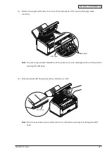
Page 20: ...Data CONFIDENTIAL 43641601TH Rev 1 20 2 3 3 LED Head 1 Open the cover assy top 2 Remove the LED head and then remove the flat cable As two head springs come off at that time be careful not to lose th...

Page 21: ...assy upper See 2 3 2 3 Remove the LED head See 2 3 3 4 Remove the screw and then remove the flat cable from the connector HEAD 5 Push the right clamp outward disengage the engaging part and then also...

Page 22: ...reful of the following Important 1 When unplugging the cable do not add the excess force If adding it solder fracture in the land of connector occurs and it causes poor connection and then extraordina...

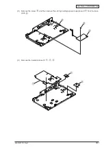
Page 23: ...hree screws 6 Remove the screw and then remove the cable and the contact CB 7 Remove the inlet of the low voltage power supply board from the frame base When removing the inlet from the frame base unl...

Page 24: ...Oki Data CONFIDENTIAL 43641601TH Rev 1 24 10 Remove the solenoid shaft 11 Disengage the engaging parts of the solenoid lever and solenoid and then remove two screws and the solenoid...

Page 25: ...Oki Data CONFIDENTIAL 43641601TH Rev 1 25 12 Disengage two engaging parts and remove the guide sheet...

Page 26: ...Oki Data CONFIDENTIAL 43641601TH Rev 1 26 13 Remove the separator assy and spring compression S 14 Remove the sensor paper E...

Page 27: ...er See 2 3 1 2 Remove the cover assy upper See 2 3 2 3 Remove five screws and disengage the engaging part of the solenoid lever and then remove the plate side M 4 Remove the earth plate two idle gears...

Page 28: ...eeder See 2 3 1 2 Remove the cover assy upper See 2 3 2 3 Remove the cover assy top See 2 3 4 4 Remove the high voltage power supply 1 sensor board See 2 3 5 5 Remove the frame base See 2 3 6 6 Remove...

Page 29: ...ove the high voltage power supply 1 sensor board See 2 3 5 5 Remove the frame base See 2 3 6 6 Remove the guide sheet See 2 3 6 7 Remove the plate side M See 2 3 7 8 Remove the guide paper F and C rin...

Page 30: ...e 2 3 2 3 Remove the cover assy top See 2 3 4 4 Remove the plate side M and then remove the idle gear R and gear R See 2 3 7 5 Remove the washer TR slide the registration roller to the right and lift...

Page 31: ...Oki Data CONFIDENTIAL 43641601TH Rev 1 31 2 3 11 Transfer Roller Assy 1 Open the cover assy top and remove the I D unit...

Page 32: ...between the latch and gear T and turn it until touching the left side Keeping the condition of the above 1 use the other screwdriver to lift up the shaft of transfer roller and then pull out the prot...

Page 33: ...aper feeder See 2 3 1 2 Remove the cover assy upper See 2 3 2 3 Remove the cover assy top See 2 3 4 4 Remove the high voltage power supply 1 sensor board See 2 3 5 5 Remove two screws and connector an...

Page 34: ...der See 2 3 1 2 Remove the cover assy upper See 2 3 2 3 Remove the cover assy top See 2 3 4 4 Remove the high voltage power supply 1 sensor board See 2 3 5 5 Remove the heat assy See 2 3 12 6 Remove t...

Page 35: ...r Assy Toner 1 Remove the paper feeder See 2 3 1 2 Remove the cover assy upper See 2 3 2 3 Remove the cover assy top See 2 3 4 4 Remove the high voltage power supply 1 sensor board See 2 3 5 5 Remove...

Page 36: ...Oki Data CONFIDENTIAL 43641601TH Rev 1 36 8 Remove the sensor paper exit 9 Bending the latch of the sensor assy toner to the arrow direction remove it...

Page 37: ...er feeder See 2 3 1 2 Remove the cover assy upper See 2 3 2 3 Remove the cover assy top See 2 3 4 4 Remove the high voltage power supply 1 sensor board See 2 3 5 5 Remove the frame base See 2 3 6 6 Re...

Page 38: ...Oki Data CONFIDENTIAL 43641601TH Rev 1 38 7 Remove four screws and cable and then remove the control board...

Page 39: ...Oki Data CONFIDENTIAL 43641601TH Rev 1 39 8 Remove the screw and then remove the sub high voltage power supply board from the base plate 9 Remove the insulation sheet C...

Page 40: ...to enable or disable the PRINT menu When set to Disable the PRINT menu of User Menu is not displayed MEDIA ENABLE DISABLE Sets whether to enable or disable the MEDIA menu When set to Disable the MEDIA...

Page 41: ...Oki Data CONFIDENTIAL 43641601TH Rev 1 41 This page intentionally left blank...

Page 42: ...Oki Data CONFIDENTIAL 43641601TH Rev 1 42 Values marked with an asterisk are default This page intentionally left blank...

Page 43: ...Oki Data CONFIDENTIAL 43641601TH Rev 1 43 This page intentionally left blank...

Page 44: ...Oki Data CONFIDENTIAL 43641601TH Rev 1 44 This page intentionally left blank...

Page 45: ...Oki Data CONFIDENTIAL 43641601TH Rev 1 45 This page intentionally left blank...

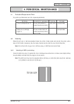
Page 46: ...or stripes void light printing are generated vertically down the page as shown below Note The LED lens array must be cleaned with a soft tissue or cloth after static electricity collected on maintenan...

Page 47: ...tricity before cleaning the LED head 1 Before cleaning the LED head touch one of the metal parts of the head to discharge static electricity 2 Wipe the whole LED head gently with a soft tissue or clot...

Page 48: ...itor displays the message MANUAL PAPER REQUEST on its upper line and the message MANUAL A4 REQUEST or MANUAL LETTER REQUEST on its lower line 3 Insert a sheet of A4 or Letter paper into the manual fee...

Page 49: ...ir image problems to be corrected 3 The print paper in printers with image problems to be corrected is of acceptable quality 4 The image drum cartridges of printers with image problems to be corrected...

Page 50: ...ceiving data or processing received data Data Received Data Received Blink 1 Off Varies in status Received data is in the printer The printer is waiting for data to be sent next Printing Printing in p...

Page 51: ...e the printer routed paper through it Open the printer s top cover to remove jammed paper Paper output jam A paper jam oc cured while eject ing paper Off Off Blink 2 A paper jam occurred in the printe...

Page 52: ...2 The printer received invalid data Press ONLINE switch Non OEM Toner detected Non OEM Toner detected Varies in status Off Blink 2 The printer is not equipped with a genuine toner cartridge but can o...

Page 53: ...nly Error deleting directory The directory is not empty Varies Varies Blink 1 The directory is not empty B2400n Only Disk error Disk error Varies Varies Blink 1 Disk error B2400n Only No label No labe...

Page 54: ...de 807 LEDs Ready then Manual and the Error from left White circle On Black circle Off Error Code Indication Upon an error with the printer its Ready Manual Error LED starts blinking Then the status o...

Page 55: ...AM Check Error Reserved 40057 032 CU Slot4 DIMM RAM Check Error Reserved 40057 033 RAM configuration error 40057 034 Slot1 RAM Spec error 40057 035 Slot2 RAM Spec error Reserved 40057 036 Slot3 RAM Sp...

Page 56: ...06 Engine ROM error Reserved 40057 107 Reserve 108 119 Engine Flash write Error Loader type Miss match 40057 110 Engine Flash write Error Program type Miss match 40057 111 Engine Flash write Error Fla...

Page 57: ...Toner Sensor Error Color Yellow Reserved 40057 160 Toner Sensor Error Color Magenta Reserved 40057 161 Toner Sensor Error Color Cyan Reserved 40057 162 Toner Sensor Error Color Black 40057 163 Reserve...

Page 58: ...06 Illegal function call 40057 207 Parameter error 40057 208 Reserved 209 EM Null page cargo 40057 210 EM Null page 40057 211 EM No video queue 40057 212 EM Illegal sequence 40057 213 Reserve 214 229...

Page 59: ...e Blink 2 500 mS cycle Blink 3 120 mS cycle Description PJL Status code Status level error code Ready Manual Error Blink 3 Blink 3 Blink 3 Instruction TLB miss 40057 009 Data TLB load miss 40057 010 D...

Page 60: ...ve section can work for a problem with a printer any of the troubleshooting flow charts shown below should be followed to solve the problem No Problem Flow Chart Number 1 Printer does not operate norm...

Page 61: ...r No Aren t the 5 V and GND on the main board short circuited check the voltages at the pins 3 and 2 of the CN18 connector No Replace the low voltage power supply Yes Replace the board Yes Is the flex...

Page 62: ...ce it Yes Clean the paper sensor on the high voltage power supply 1 sensor board or replace the board No Replace the hopping roller or the paper cassette that is to input paper No Does the hopping rol...

Page 63: ...ly Yes Does paper reach the outlet sensor plate Yes Does the plate function properly does it move freely when it is touched No Replace it Yes Clean the outlet sensor on the high voltage power supply 1...

Page 64: ...the printer is turned on Yes Is there paper on the outlet sensor plate Yes Remove the paper No Does the outlet sensor plate function properly does it move freely when it is touched No Replace it Yes...

Page 65: ...sor plate function properly does it move freely when it is touched No Replace it or clean the paper sensor on the high voltage power supply 1 sensor board Yes Does the outlet sensor plate function pro...

Page 66: ...he thermistor connector into the CN2 connector properly Yes Is the heat connector inserted into the CN202 connector of the low voltage power supply properly No Insert the heat connector into the CN202...

Page 67: ...ced image Dirty background White paper Vertical black belt line Periodic pattern Vertical white belt line Problem Flow Chart Number Light or entirely faded image figure 5 2 Dirty background figure 5 2...

Page 68: ...wer supply 1 sensor board properly see figure 5 3 No Adjust the plate so as to make it in good contact with the board and the transfer roller shaft Yes Are the contact of the developing roller and the...

Page 69: ...act with the assembly Yes Replace the cartridge Did this step work Yes End Note Reset the drum counter after the cartridge is replaced see the user documentation No Replace the main board or the high...

Page 70: ...in board or the high voltage power supply 1 sensor board Periodic pattern Note Reset the drum counter after replacing the image drum cartridge see the user documentation Interval Solution Image drum 5...

Page 71: ...ead No Install the head properly Yes Replace the head or the head cable Did this step work Yes End No Replace the main board or the high voltage power supply 1 sensor board Poor fusing text or image b...

Page 72: ...p work Yes End Yes Is the tension between the back up roller 7 52 kg and its surface proper No Replace the back up roller or the bias spring Yes Is the LED head installed properly check the CN5 connec...

Page 73: ...41601TH Rev 1 73 Figure 5 3 Charging roller Contact Toner supply roller Cleaning roller Ground drum Ground drum Cleaning roller Developing roller Charging roller Toner supply roller Developing roller...

Page 74: ...Thermistor in Fuser Unit Sub High Voltage Power Supply CB Solenoid High Voltage Power Supply Output High Voltage Power Supply Output TR S5 S6 S7 S12 S8 S13 S11 S16 SB DB CH CN4 CN1 CN202 CN101 CN1 CN...

Page 75: ...Data CONFIDENTIAL 43641601TH Rev 1 75 6 2 PCB Layout 1 Main Control Board Printer Front Side Printer Front Side Contact Face LED Head LED Panel Board Printer Front Side LED Head Cable PC Connector 14...

Page 76: ...4 Black 1 Orange 3 Brown Excitation sequence Direction of rotation Clockwise as viewed from the output shaft Pin No I O Signal Function 1 1 O CLTON Power Supply for clutch Driving 2 2 C DGND Ground fo...

Page 77: ...HDDATA1 Data 1 10 10 O HDDATA0 Data 0 11 11 O HSTB N Strobe 0 12 12 O HSCK Strobe 3 13 13 O HSO Strobe 2 14 14 O 3 3VCC 3 3 Power Supply for Logic 15 15 C LED_GND Ground for LED 16 16 O HEAD Power Sup...

Page 78: ...ssignment To Operator Panel I In O Out C Common Pin No I O Signal Function 1 1 O 5V 5V Power Supply 2 2 O LED1 P LED1 ON 3 3 I SW1 N Switch Data 4 4 O LED2 P LED2 ON 5 5 NC NC Non Connection 6 6 O LED...

Page 79: ...ic 11 11 I THERM Thermistor Temp 12 12 C DGND Ground for Logic 13 13 I TRI_FB TR1 Current Detection 14 14 I TRV_FB TR1 Voltage Detection 15 15 I DB2_V_FB DB2 Voltage Detection 16 16 I CHI Frame Thermi...

Page 80: ...ON N Heater On 7 7 C DGND Ground for Logic 8 8 I HEAD LED Head Power Supply 9 9 I HEAD LED Head Power Supply 10 10 C LED_GND LED Head Ground 11 11 C LED_GND LED Head Ground 12 12 C DGND Ground for Log...

Page 81: ...2 I O D Serial Data 3 I O D Serial Data 4 C GND Logic Ground JP2 Connector Pin Assignment To LAN I F Pin No I O Signal Function 1 O TX Transmitting signal output 2 O TX Transmitting signal output 3 I...

Page 82: ...ATA4 P Data Bit 4 24 C SG Logic Ground 7 25 7 C DATA5 P Data Bit 5 25 C SG Logic Ground 8 26 8 C DATA6 P Data Bit 6 26 C SG Logic Ground 9 27 9 C DATA7 P Data Bit 7 27 C SG Logic Ground 10 28 10 O ACK...

Page 83: ...Oki Data CONFIDENTIAL 43641601TH Rev 1 83 2 High Voltage Power Supply 1 Sensor Board PS1 SW2 CN2 CN1 PS2 PS6 PS3 CN4...

Page 84: ...11 11 O THERM Thermistor Temp 12 12 C DGND Ground for Logic 13 13 O ISEN TR1 Current Detection 14 14 O VSEN TR1 Voltage Detection 15 15 O DB_V_FB DB2 Voltage Detection 16 16 O CH_I CH Current Detecti...

Page 85: ...onnector Pin Assignment To Tag in Toner Cartridge I In O Out C Common I In O Out NC Non Connection C Common Pin No I O Signal Function 1 1 O 5V 5V 2 2 NC NC Non Connection 3 3 I THERM Thermistor Volta...

Page 86: ...CN3 Connector Pin Assignment To Main Control Board Pin No I O Signal Function 1 1 C DGND Ground for Logic 2 2 I CB2PWM P CB2 Output 3 3 I CB1PWM P CB1 Output 4 4 I H5V 5V Power Supply T1 D134 D133 D13...

Page 87: ...Oki Data CONFIDENTIAL 43641601TH Rev 1 87 4 Low Voltage Power Supply...

Page 88: ...5V Power Supply 5 5 O 5V 5V Power Supply 6 6 I HEAT_ON N 5V Power Supply 7 7 C DGND Ground for Logic 8 8 O HEAD LED Head power supply 9 9 O HEAD LED Head Power Supply 10 10 C LED_GND LED Head Ground 1...

Page 89: ...ration Resistance Pulse Motor Main Orange Yellow Brown Black M 1 2 3 4 Between Pins 1 and 2 3 2 Between Pins 3 and 4 3 2 Fuser Assy Between Pins 1 and 3 1 6 Between Pins 1 and 3 360k 5 at room tempera...

Page 90: ...D29A made by Daiichi Denshi or equivalent Cable side 36 pin plug male Type 57FE 30360 20N D8 made by Daiichi Denshi or equivalent 2 Cable Use an IEEE Std 1284 1994 compliant cable or equivalent with...

Page 91: ...l indicating whether the printer is ready to receive data or not When the signal is at high level the printer is not ready to receive data 12 Perror AckDataReq FROM PRINTER This signal becomes high le...

Page 92: ...Power ON Notice of Transition to Online PError H L H L H L H L H L nAck Busy nFault Select Receive DMA Starting Receive DMA PEND RUNNING b Power ON Menu setting PARALLEL DISABLE Item Description Mode...

Page 93: ...Menu setting Ack Busy Timing Ack while Busy e I Prime Menu setting I PRIME DISABLE Idle Idle Initializing I F Cleaning Send Receive Buffer nInit H L H L Busy T INIT Canceling Job Printer Status Menu...

Page 94: ...Select Receive DMA PEND RUNNING RUNNING Printer Status Paper End Restarting Receive DMA Terminating Receive DMA Notice of Transition to Online Notice of Transition to Paper End Online Idle Busy H L H...

Page 95: ...le Upstream port USB 4R D14T 1 made by J S T Mfg or equivalent Cable side B plug male 2 Cable Use a USB2 0 cable with a length of 2 0 m max A shielded cable is recommended Note No cable is supplied wi...

Page 96: ...ferential 0 D D 200 mV and D VIH min D D 200 mV Single ended 0 SE0 D and D VIH max D and D VIH min Data J state Low speed Full speed Differential 0 Differential 1 Data K state Low speed Full speed Dif...

Page 97: ...Protocols Used for Setup Reference 2 and Change 3 Other Protocols TCP IP LPR Port 9100 HTTP SNMP DHCP BOOTP AutoIP DNS TCP IP ICMP ARP UDP APPENDIX C NETWORK INTERFACE 1 Connector 8 pin modular jack...

Page 98: ...t Log in name of the user that has called the LPR User name printed on the banner sheet J Specify by J option Job name printed on the banner sheet Default File name C Specify by C option Job type prin...

Page 99: ...an IP address such as a DHCP server does not exist on the network the IP address will be 169 254 xxx xxx even when the network cable is connected to the hub Host Name Product name Last 6 digits of Eth...

Page 100: ...HALF 10BASE T FULL 10BASE T HALF Web Port No 80 Printer Setup Web ENABLE Sets whether to enable disable access through a Web browser in the printer DISABLE Web 1 Sets a port number to gain access to t...

Reviews: