background image


7


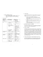
TROUBLESHOOTING 

 
PROBLEM POSSIBLE 

CAUSE CORRECTION 

LCD does not 
light 


No power input 


Check power cord 
connections 


Turn on power 


System will not 
actuate 


Foot switch not 
plugged in or 
improperly plugged 
in 


Defective foot switch 


Broken wire or loose 
connection inside 
unit 


Defective solenoid 


Defective PC board 


Check foot switch 
connection 


Foot switch needs to be 
repaired or replaced 


Unplug power cord and 
disconnect air supply.  
Remove cover and check 
for broken wires or loose 
connections 


Replace solenoid 


Replace PC board 

System will not 
pressurize 


Insufficient air 
pressure 


Air hoses not 
plugged in 


Regulator defective 


Increase air supply 
pressure 


Check connection 


Replace regulator 

System will not 
pull vacuum 


Vacuum setting is 
too low 


Defective solenoid 


Defective vacuum 
venturi 


Defective vacuum 
needle valve 


Increase vacuum setting 


Replace solenoid valve 


Replace venture 


Replace needle valve 

Inconsistent 
dispensing 


Air bubbles in 
adhesive 


Dispense time is too 
low 


Dispense needle 
started to clog 


Reduce vacuum setting 


Increase dispensing time 


Replace needle 


8

8


MAINTENANCE  


The dispenser is designed and built to be relatively maintenance free.  To assure 
trouble free operation, the following recommendations should be followed: 

1.


Make certain air supply is clean and dry 

2.


Avoid turning barrels upside down or laying barrel so that material may 
run through air line to internal components 

3.


Avoid connecting the unit to excessive moisture or solvent saturation. 

4.


Avoid connecting air supply exceeding 100 psi (6.9 bar) for the DX-350 
and 15 psi (1.03 bar) for the DX-355 

5.


Use only Amyl Alcohol to clean outside surface of the main housing. 

6.


Use only soft cloth to clean the LCD 


9


SPARE PARTS  AND ACCESSORIES 


For DX-3xx/2xx spare parts and accessories information, please visit the DX-
3xx/2xx User Guide webpage at 

http://www.okinternational.com


10


LIMITED WARRANTY 

 
OK International warrants this product to the original purchaser for a period of one 
(1) year from date of purchase to be free from material and workmanship defects but 
not normal wear-and-tear, abuse and faulty installation.  Defective product or 
subassembly and components under warranty will be repaired or replaced (at OK 
International's option) free of charge. Customer with defective product under 
warranty must contact the nearest OK International office or distributor to secure a 
return authorization prior to shipping the product to the assigned OK International 
authorized service center.  For nearest OK International office or distributor contact 
information, please visit www.okinternational.com.  OK International reserves the 
right to make engineering product changes without notice. 
 

11


I/O Configuration and End of Cycle Switch 


For DX3xx/2xx I/O Configuration and End of Cycle Switch information, please visit 
the DX-3xx/2xx User Guide webpage at 

http://www.okinternational.com

Summary of Contents for DX-350 / 355

Page 1: ...rm taking the following actions Making changes to equipment that has not been recommended in the User Guide Using incompatible or damaged replacement parts Using unapproved accessories or auxiliary eq...

Page 2: ...to 31 C 87 8 F Decreasing linearly to 50 relative humility at 40 C 104 F Air Output DX 350 0 100 psi 0 6 9 bar DX 355 0 15 psi 0 1 03 bar Vacuum 406mm 16 of Hg Timer 0 008 60 000 seconds Cycle Mode T...

Page 3: ...e 4 Depress Foot switch to activate timed dispensed cycle 6 3 Teach Mode Setting In the teach mode the unit will accumulate time as long as the foot switch is depressed This is helpful in determining...

Page 4: ...barrel so that material may run through air line to internal components 3 Avoid connecting the unit to excessive moisture or solvent saturation 4 Avoid connecting air supply exceeding 100 psi 6 9 bar...

Page 5: ...Nennleistungen Einstellungen Tragen Sie immer geeignete Schutzkleidung Verwenden Sie nur die folgenden Adaptertypen PSA15R 240P ZJ oder PW118RA2403B01 PW118RA2403H01 PW118RA2403M01 PW118RA2403G01 Ach...

Page 6: ...9 bar DX 355 0 15 psi 0 1 03 bar R ckhaltevakuum 406 mm 16 Hg Timer 0 008 60 0 Sekunden Zyklusbetrieb Zeiteinstellmodus mit Unterbrechung Sp len Lern Modus Wiederholtoleranz 0 001 Zyklen geschwindigk...

Page 7: ...rammeinstell Regler 8 um zwischen den 10 m glichen Dosierprofilen zu w hlen Positionen Beschreibung 1 zur Druckluftversorgung 2 Luftfilter Nicht im Lieferumfang enthalten 3 Netzadapter 4 Fu schalter 7...

Page 8: ...Taste 3 bis der Doppelpunkt inter dem Wort PRESSURE oder VACUUM im Display blinkt 2 Drehen Sie den Programmeinstell Regler 8 bis der gew nscht Wert im Display angezeigt wird 9 7 FEHLERBESEITIGUNG PRO...

Page 9: ...des Zyklus Informationen zur I O Konfiguration und Zyklusbeendigung des DX 3xx 2xx finden Sie auf der OK InternationalWebseite des Benutzerhandbuchs DX 3xx 2xx unter http www okinternational com 2 SOM...

Page 10: ...000m 6 562ft Temp rature d utilisation 0 C 50 C 32 F 122 F Temp rature de stockage 10 C 60 C 14 F 140 F Humidit relative maximale 80 pour des temp ratures jusqu 31 C 87 8 F avec d croissance lin aire...

Page 11: ...urnez le bouton de r glage 8 pour choisir le temps de dosage desir 3 Rel chez la p dale pour activer le cycle de dosage temporis 4 Appuyez sur la p dale de commande pour d clencher le cycle de dosage...

Page 12: ...ne s coule pas travers la ligne d alimentation en air vers les composants internes 3 vitez de soumettre l appareil une humidit ou une saturation de solvant excessive 4 Ne raccordez pas d alimentation...

Page 13: ...corrosivi o infiammabili occorre installare un filtro in linea 881 000 000 sul dosatore per prevenire il risucchio dei fluidi all interno dell unit Il fluido erogato potrebbe essere tossico e o perico...

Page 14: ...NSTALLAZIONE Fare riferimento alla figura 1 0 6 1 Impostazione del ciclo di dosatura manuale spurgo 1 Accendere l apparecchio premendo l interruttore principale 1 2 Premere il pulsante di selezione de...

Page 15: ...nterruttore a pedale una volta erogata la quantit giusta di fluido 5 Premere il pulsante di selezione 2 per passare alla modalit TIMED 6 A questo punto il dosatore impostato per ripetere questo ciclo...

Page 16: ...alimentazione sia pulita e secca 2 Non ribaltare i cilindri n adagiarli su di un fianco onde evitare il riflusso di materiale attraverso il tubo dell aria fino ai componenti interni 3 Non esporre l a...

Page 17: ...un filtro en l nea 881 000 000 en el dosificador para impedir que los l quidos sean succionados nuevamente a la unidad El l quido que se dosifica puede ser t xico y o peligroso Consulte las instrucci...

Page 18: ...da la unidad presionando el bot n de encendido 1 2 Presione el bot n de modo 2 hasta que aparezca el texto PURGE en la pantalla 3 Active la presi n de aire girando la perilla del regulador de aire a p...

Page 19: ...dosificado la cantidad apropiada de l quido 5 Presione el bot n de modo 2 para cambiar al modo TIMED 6 El dosificador est configurado ahora para repetir este ciclo de tiempo 7 6 4 Configuraci n para d...

Page 20: ...horizontal de modo que el material pudiese correr a trav s de una l nea de aire hacia los componentes internos 3 Evite conectar la unidad con excesiva humedad o saturaci n de solventes 4 Evite conecta...

Reviews: