background image

28

Alarms > Routing schedule

Routing schedule

S203 default alarm groups are:

•  Group 1: 

Urgent alarm that should always be immediately 

routed.

•  Group 2: 

Malfunction alarms than can be frouted during busi-

ness hours. 

•  Group 3:

 Service alarms or non-urgent alarms. 


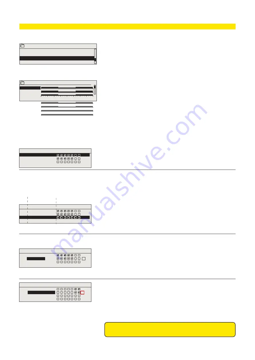
You can see where alarms are currently being routed  from 

the routing schedule menu. You can also set up a routing 

schedule for each alarm group. 

You can create a weekly schedule for each alarm group. 

Weekly schedule have a general graphic view and an editing 

view, where you can see to which alarm team each alarm is 

sent at different times. In the graph, alarm teams are distin-

guished from each other by the bars with different thickness.

Editing view

Time  Mode

Time   Mode

Time Mode

M   T  W   T  F S  S

M  T W  T  F  S  S

M  T  W T  F  S  S

OK

Deleting a switch time:

1.  Turn the control knob to navigate to the switch time you wish to 

delete and press OK. 

2.  Press OK at the alarm team and select ”Delete switch time” 
3.  Press OK at the end of the row.
4.  To exit edit mode, press ESC.

1.   Set switch time

2. Set alarm team

3.Select day(s)

Time Mode
08:00 Team 1
21:00 

Delete switch time

00:00 Add new

M   T  W  T F S  S

OK

Browsing a weekly schedule:

An editing view opens, and it shows all the switch times and also to 
which alarm teams alarms are routed at these times on the chosen 
days.

Turn the control knob to browse a weekly schedule. If you wish to
see the exact switch times and names of alarm teams, or if you
wish to edit, remove or add switch times, press OK at any weekday.

Adding a new switch time:

1.  Press OK at the “Add new” row.
2.  Press OK. Set the switch time for alarm routing (set hours and 

minutes separately) and press OK.

3.  Press OK and then turn the control knob to set the alarm team or 

the ”No routing” option.  (No routing option means that alarms will 
not be sent.) Accept by pressing OK.

4.  Press OK at desired weekdays you wish to choose. 
5.  Press OK at the end of the row to accept the created schedule. 
6.  Press Esc to exit.

Editing a weekly schedule:

1.  Turn the control knob to navigate to the value you wish to change 

and press OK. 

2.  Turn the control knob to make the time and alarm team changes. 

Press OK to accept. 

3.  Press the OK button to change the day of the week. 
4.  Press Esc to exit.

Graph

This example shows that group 1 alarms are 

always forwarded. During business hours 

(Monday - Friday 8:00 a.m. - 4:00 p.m.) alarms 

are forwarded to different teams than during 

evenings and weekends. More detailed 

information is shown in the ”Editing view”.

Monday      >
Tuesday     >
Wednesda  >

Thursday    >
Friday         >
Saturday   >
Sunday       >

 3 

 6 

 9 

 12 

 15 

 18 

 21 

 24

Group 1 Weekly schedule

08:00 Team 1

16:00  Team 2
00:00  Add new

08:00 Team 1
16:00 Team 2

00:00 Add new

08:00 Team 1
16:00

 No routing

00:00 Add new

Routing schedule

Group 1 Weekly schedule
Group 1 Alarm routing now                        Team 1

Group 2 Weekly schedule
Group 2 Alarm routing now                        Team 1

>
>

>
>

Alarms are routed according to the routing schedule. You can ac-
knowledge an alarm by forwarding the same message to the S203.

Summary of Contents for S203

Page 1: ...Controller for three circuits control for 2 heating circuits 1 domestic hot water control USER MANUAL USER MANUAL S203 OILON L MP SS YM0055 Version1 0...

Page 2: ...sons in maintenance or who has in depth knowledge of the control process The S203 is a heating controller for 3 circuits two heating circuits and one hot water circuit Wiring and configurating selecti...

Page 3: ...trol 18 4 1 Time programs 20 5 Distribution valve control 22 6 Geothermal heating 22 6 1 Setting values 22 6 2 Status 23 7 Alarms 25 8 System settings 29 8 1 Setting date time and language 29 8 2 Text...

Page 4: ...information for monitoring operation of the unit Favourite views that can be changed by us ers enable them to easily access desired menus Setting values needed by the user can easily be found in the v...

Page 5: ...m signal stops and the last alarm windows disappear from the display You may look into the alarms later by going to Alarms Active alarms If an alarm has not been acknowledged an exclamation mark will...

Page 6: ...Heating curve Setting values Control mode Time programs Automatic Automatic DHW Domestic hot water control Info Setting values Control mode Automatic Alarms Active alarms Alarm history Acknowldge all...

Page 7: ...rn water 22 0 C H1 Room temperatur 21 5 C H1 Actuator control 22 H2 Supply water 28 1 C H2 Return water 21 1 C If a GSM modem is connected to the controller you can read measure ment information with...

Page 8: ...ng Outdoor temperature M1 H1 Supply water M2 H2 Supply water M5 Accumulator upper part M10 Accumulator lower part M11 Hot gas temperature M12 Compressor s running information NO M13 P2 Pump Alarm Indi...

Page 9: ...sist r Heating boiler Changing valve VV Domestic water connections Domestic hot water boiler M2 M10 M11 M12 M7 Act 2 Act 1 M5 H1 H2 Measurement Range Measurement information Geopro SH H1 Supply water...

Page 10: ...the pre increase operation can in crease the temperature of supply water Force control effect Supply water has been forced permanently to the desired temperature reduction level see Control mode selec...

Page 11: ...t measured supply water temperature Outdoor temp The measured outdoor temperature Outdoor temperature data is displayed if the delayed outdoortemperatureisnotusedinsupplywatercontrol Delayed outdoor t...

Page 12: ...at the outdoor temperatures 20 C 10 C and 0 C Setting Factory setting Explanation 5 point curve Heating curve 20 58 C 0 41 C 20 18 C Min limit 18 Max limit 75 10 50 C 10 28 C 20 20 0 C 20 40 60 80 Wi...

Page 13: ...ax limit 45 20 20 0 C 20 40 60 80 1 Radiator heating normal default Heating curve 20 50 C 0 37 C 20 18 C Min limit 18 Max limit 75 10 44 C 10 28 C 20 20 0 C 20 40 60 80 2 Radiator heating steep curve...

Page 14: ...on and the valve returns back to control mode Pump summer stop In use In use Not in use If the controller is connected to control the pump the pump can be stopped when the summer function is active V...

Page 15: ...configuration H1 H2 Actuator control Manual mech control Available If you want the voltage controlled actuators to be controlled by manu al mechanical control H1 actuator power supply must come from...

Page 16: ...reases supply water temperature at the end of the reduction phase Normal temperature has already been reached when the heating mode changes to normal heat Set switch time Set state desired temp level...

Page 17: ...program 3 5 3 Special days You can enter special day programs as exceptions to normal week ly schedule You can designate a maximum of 7 special day po grams SD A special day program is typically crea...

Page 18: ...er control Info menu shows the domestic hot water settings the measure ments and actuator control related to the domestic hot water DHW Control circuit Info Setting values Control mode Automatic Trend...

Page 19: ...sition 20 Manual mechanical Manual mechanical control option must be taken into use Connections and configuration DHW Actuator control Manual mech control Available If you want the voltage controlled...

Page 20: ...rately Press OK to accept 3 Press OK and then turn the control knob to set the temperature level Drop ON Increase ON normal Press OK to accept 4 Press OK at each weekday you wish to choose 5 Press OK...

Page 21: ...edule You can designate a maximum of 7 special day po grams SD A special day program is typically created for each holiday When the special day program will be applied it is set in the exception sched...

Page 22: ...splay shows the top input setpoint and the measured temperature as well as the desired actuator position The control of the distribution valve is normally automatic but it can also be manual controlle...

Page 23: ...sed heating time the temperature of the hot domestic water boiler s lower part is raised to the set value at measuring point 11 This function can be activated with a separate switch placed e g in the...

Page 24: ...eating water leaving the geothermal appliance Extra heating Extra heating time 50 2 40 55 C 0 6h When the Extra heating button is pressed the setting changes from Boiler down MIN limit to the Extra he...

Page 25: ...out of use Informational measurement 10 s 10 s 1 s 2 2 2 2 5 TMW TMS Sensor fault H2 Supply water Valve remains in the position it was in before the sensor defect 20 s 1 s 1 1 6 TMW TMS Sensor fault...

Page 26: ...d by the electric ity distribution cabinets or the low pressure pressostate acknowledged by the pressostat Geopro GS Controller is not receiving the running information from the compressor even it sho...

Page 27: ...The controller sends a message showing the last 10 alarms Message is informational Alarm receivers Alarm history Alarm receivers Reset alarm history ACTIVE ALARMS Every active alarm is shown in a sep...

Page 28: ...e the exact switch times and names of alarm teams or if you wish to edit remove or add switch times press OK at any weekday Adding a new switch time 1 Press OK at the Add new row 2 Press OK Set the sw...

Page 29: ...1 Set day and press OK to accept name of weekday is updated au tomatically 2 Set month and press OK to accept 3 Set year and press OK to accept 4 To exit without saving and changes press Esc The langu...

Page 30: ...troller sends a message where is a list of key words text message communication is ok If the controller doesn t send a text message enter the message center number makepowercutandturnitback Retestthet...

Page 31: ...date network settings System settings Network settings System settings Time 17 01 Date 10 12 2020 Language English SMS settings Network settings Display settings Type info Lock code Not in use Backup...

Page 32: ...f you know DHCP service exists in the network if you wish to use a fixed IP address 1 First set DHCP function On After the settings have been set successfully set DHCP Off 2 Change only IP address man...

Page 33: ...rom any port to the port 123 and the receipt of the reply message to this port Access Oulink and M Link supports Ouman Access service which gives you a secure remote connection to the S203 device With...

Page 34: ...ode The factory set ting of lock code is 0000 2 Turn the control knob and press OK to accept each number Press ESC to return to the previous square 3 Press OK for a number of seconds to accept the cod...

Page 35: ...lay is connected to S203 to RJ 45 port II Cable max length 10 m External display 2 3 11 12 20 13 21 14 22 15 23 16 24 17 25 18 26 19 27 28 1 5 6 31 32 40 33 41 34 42 35 43 36 44 37 45 38 46 39 47 48 4...

Page 36: ...trolled actuator 2 serial driving 24 VAC 24 VAC 53 55 56 63 65 65 54 3x0 8 3x0 8 3x0 8 0 10V DC ctrl 0 10V DC ctrl Open Close AO1 AO2 Y1 output Y2 output TR1 TR2 Actuators control of H1 Heating circui...

Page 37: ...VAC 2x0 8 A1 NO 10 VDC output C NC A2 66 Y4 67 120 120 BG A1 A2 Master device S203 Slave device Data Data 3 5 6 A BG B The controller uses a 230 VAC operating volt age whereby the power supply is sup...

Page 38: ...uration Check the functions which have been taken in use in the controller X If the measurement shows 0 5 C too much set the offset to 0 5 C You can choose between the measurement channels M1 to M13 a...

Page 39: ...controller sets pump on but it s not started The alarm has a 5 s delay Pump alarm Nameable alarm M16 Alarm 16 Indication P3 Indication Name P3 Pump P3 Alarm Alarmpriority___ 1 Emergency Digital input...

Page 40: ...Running time factory setting setting range H1 Actuator control AO1 AO1 0 10 V 2 10 V 10 0 V 10 2 V 3 point TR1 TR2 Running time open ____ 150 s 10 500 s Running time close ____ 150 s 10 500 s H2 Actu...

Page 41: ...he factory default setting for the damping point is 7 C At a value setting of more than 17 C parallel shift damping is not enabled the function is not available if room temperature mea surement is con...

Page 42: ...controller indicated H1 supply water temperature 5 C and the temperature of the controller s lower part meas 11 rises above the Accumulator Lower part MIN Accumulator Lower part hysteresis temperature...

Page 43: ...the compressor every 60 minutes The electrical heating resistor switches off when the temperature of the accumulator s upper part meas 10 rises above the Upper part setting Accumulator Upper part hyst...

Page 44: ...r Upper part MIN Accumulator Upper part hyster esis and the temp of the accumulator s lower part meas 11 exceeds the controller indicated temp of H1 supply water 5 C and the temp of the accumulator s...

Page 45: ...1 4 C and the temperature of the accumulator s lower part meas 11 is above Accumulator Upper part MIN Accumulator Upper part hysteresis and the temp of the accumulator s lower part meas 11 exceeds the...

Page 46: ...set to a higher level and the capacity for the hot domestic water increases The activated time for the switch HW Extra heating time can be set in the set values Freezing alarm In the freezing alarm ca...

Page 47: ...ement 12 has reached controller indicated H1 supply water temperature 4 C and When HW Extra heat is activated and the temperature of the measurement 11 has reached the Hot water HW Extra heat The comp...

Page 48: ...55 C When the temperature of the lower part of the boiler meas 10 is exceeded this setpoint always stops the compressor even if the top of the boiler commands the compressor to start Boiler Top hyste...

Page 49: ...ches ON according to the Boiler Top temperature when meas 10 is lower than Boiler Top setting Hot water hysteresis Boiler Top hysteresis heating resistor The electrical heating resistor switches OFF a...

Page 50: ...om Inputs and Outputs menu Delay function of radiator heating Outd temp delay on temp drop 0 0 0 15 h Outdoor temperature delay is in use if the radiator heating is se lected as a heating mode in the...

Page 51: ...is automatically raised for 20 days The function is turned on automatically when the average daytime temperature has been more than 7 C for a minimum of 20 days and then falls below 7 C The function r...

Page 52: ...unt of difference between measured supply water tempera ture and the supply water temperature set by the controller that causes an alarm when the deviation has continued for the entry delay time A dev...

Page 53: ...at 100 I time 14 5 300 s The deviation in the supply water temperature from the set value is corrected by P amount in I time D time 0 0 100 s Regulation reaction speed up in the event of a temperatur...

Page 54: ...ckup that it has created Software updates S203 memory card The controller automatically creates backup every hour to the con troller s internal memory and also to the memory card if the control ler ha...

Page 55: ...no electricity Open the front cover screws and remove the front cover Release the display unit by pressing down firmly supports If required use a sharp weapon Detach the display unit carefully by pryi...

Page 56: ...sed on line control room for professional remote control and monitoring optional Local Web Server remote control and monitoring M LINK optional Use of a GSM phone requires that the GSM modem optional...

Page 57: ...formational H1 Setting values H2 Setting values The most important setting values are shown in the reply message You can change the setting values by modifeing the text message and sending it back to...

Page 58: ...The modem s indicator light shows what mode it is in Inserting the SIM card Press the small black SIM card release button with for example a pen tip Part of the SIM card slot will stick out of the mo...

Page 59: ...parately from other waste to prevent damage caused by uncon trolled waste disposal to the environment and the health of fellow human beings The users must contact the retailer responsible for having s...

Page 60: ...ching current 1 5 mA inputs 27 and 28 switching current 0 5 mA inputs 25 and 26 Transfer resistance max 500 closed min 11 k open Analog outputs 53 54 64 66 68 70 Output voltage range 0 10 V Output cur...

Reviews: