


EN 10
7000 SERIES INDICATORS
Table 1-5: Switch 1 Functions
Switch
Functions
Notes
SW1-1
Metrology Security Switch
(legal for trade)
When in the ON position, this switch prohibits changes to
metrological parameters in setup. This must be ON for
“approved” applications
This is true even if the Scale
Approval parameter is selected
as “None” in setup.
SW1-2
Master Reset
Set in the ON position and power cycle to perform a master
reset of all data in the terminal
Set in the OFF position during normal operation.
When a Master Reset is
performed, set SW1-4 to ON to
reset metrologically significant
data, such as scale calibration,
GEO code, etc.
SW1-3
Flash Software
Set in the ON position for software download
Set in the OFF position during normal operation
SW1-4
Reset Calibration
Set in the ON position to reset calibration during a master reset
Set in the OFF position to retain current calibration values
during a master reset
Works with switch SW1-2
SW1-5
Not used
SW1-6
Not used
When both SW1-2 and SW1-4 are positioned ON and AC power is applied to the terminal, a Master Reset function
will be initiated. This procedure will erase all programming in the terminal and return all settings back to factory
default values. This process is described in the T72XW Technical Manual, Chapter 4,
Service and Maintenance
.
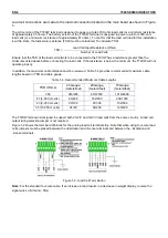
SD Card Installation
The SD memory card can be used for additional storage in the Checkweighing and Counting applications, and
must be installed if the Vehicle Application is used. Figure 1-6 shows the installation of an SD card into the socket
on the edge of the T72XW main board.
Figure 1-6: Sliding an SD Card into the SD Socket (left); SD Card Installed (right)
Capacity Label Instructions
The regulations in some locations require that the scale capacity and increment be shown on the front of the
terminal, near the display. To satisfy this requirement, a blue capacity label is included with the terminal that must
be completed and adhered to the front overlay.
The capacity label (shown in
Figure 1-7) provides space for the Max, min, and e information for both ranges for which the scale is programmed.
If only one range is used, the unused portion of the label may be cut off with scissors. Written information must be
legible and a minimum of 2mm or 0.08 in. in height. A permanent marker should be used for this information.
Figure 1-7: Preparing the Capacity Label
Summary of Contents for 7000 Series
Page 1: ...7000 Series Indicators Instruction Manual T72XW...
Page 2: ......
Page 3: ......
Page 4: ......
Page 87: ...7000 SERIES INDICATORS EN 81...
Page 96: ...EN 90 7000 SERIES INDICATORS...
Page 133: ......