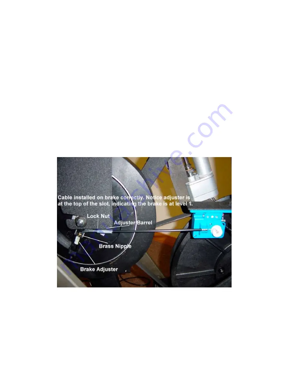
3.10 Brake Cable Adjustment
1. Using the Level - button, make sure the resistance is set to level 1 (the lowest level).
2. Unplug the unit and remove the shrouds to access the inside.
3. Check that the brass nipple at the end of the brake cable rests in the slot of the tension slide housing.
4. The brake adjuster must be at the top of its slot (toward the center of the flywheel) at resistance level 1, as shown
in Figure 3.19. If it is not at the top of the slot, free up the cable-adjusting sleeve by backing off (loosening) the
lock nut.
5. Rotate the adjuster barrel to make sure the brass nipple and the brake adjuster are touching.
6. Turn the adjuster barrel so that the brake adjuster is all the way at the top of the tension slide housing.
7. Retighten the lock nut to hold the adjuster barrel in place.
8. Plug in the unit and use the Level +/- buttons to test resistance changes, making sure the brake adjuster returns
to the top of the slot when the machine is at level 1.
Figure 3.19
Q45 3.10
Summary of Contents for Q45
Page 1: ...Q45 Q45e Q45ce ...
Page 2: ......
Page 4: ......
Page 5: ...Notes ...
Page 6: ...Figure 1 1 Figure 1 3 Right Clevis Notice step orientation to outside of machine Figure 1 2 ...
Page 8: ...Q45 1 2 Figure 1 4 ...
Page 12: ...Figure 2 2 Figure 2 3 Figure 2 1 Q45 2 1 ...
Page 14: ...Figure 2 5 Q45 2 2 Figure 2 6 ...
Page 16: ...Figure 2 7 Q45 2 2 Figure 2 8 Nylock nut Clevis bushing Figure 2 9 ...
Page 18: ...Q45 2 2 Figure 2 11 Figure 2 12 Figure 2 10 ...
Page 20: ...Q45 2 2 Figure 2 13 Figure 2 14 Figure 2 16 Figure 2 15 ...
Page 22: ...Q45 2 2 Figure 2 20 Figure 2 19 Figure 2 17 Figure 2 18 ...
Page 24: ...Figure 2 22 Q45 2 3 Figure 2 21 Speed Speed Sensors Sensors ...
Page 26: ...Q45 2 3 Figure 2 27 Figure 2 25 Figure 2 23 Figure 2 24 ...
Page 28: ...Figure 2 28 Figure 2 27 Figure 2 29 ...
Page 30: ...Figure 2 30 Figure 2 32 Figure 2 31 ...
Page 38: ...Q45 2 5 Figure 2 41 ...
Page 40: ...Q45 2 5 Figure 2 42 ...
Page 42: ...Q45 3 1 Figure 3 1 ...
Page 44: ...Q45 3 1 Notes ...
Page 46: ...Q45 3 2 Notes ...
Page 48: ...Figure 3 7 Q45 3 4 Figure 3 6 Stability Link 18mm Bolt ...
Page 54: ...Q45 3 6 Notes ...
Page 56: ...Q45 3 8 Figure 3 14 Figure 3 15 ...
Page 58: ...Figure 3 16 Figure 3 17 Figure 3 18 Q45 3 9 ...
Page 60: ...Q45 3 9 Notes ...
Page 62: ...Q45 3 11 Figure 3 21 Figure 3 20 Figure 3 22 Older units Newer units ...
Page 64: ...Q45 3 12 Figure 3 24 Figure 3 23 ...
Page 66: ...Figure 3 26 Figure 3 25 Speed Sensors Q45 3 13 ...
Page 68: ...Notes Q45 3 13 ...
Page 70: ...Q45 3 15 Figure 3 29 Figure 3 28 ...
Page 72: ...Q45 3 15 Notes ...
Page 74: ...Q45 3 17 Figure 3 31 Figure 3 32 Figure 3 33 ...
Page 76: ...Q45 3 18 Figure 3 34 Figure 3 35 Figure 3 36 ...
Page 78: ...Q45 3 19 Figure 3 37 Figure 3 38 ...
Page 80: ...Q45 3 20 Figure 3 39 Figure 3 41 Figure 3 40 ...
Page 82: ......


