Messages
Chapter 5
WAAS GUS Signal Generator User Guide Rev 1
35
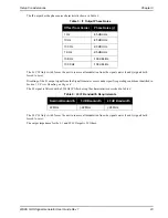
CARRIER FREQUENCY RAMP FIELD
This field is a 24 bit signed value (2’s complement) where the most significant bit (D23) is the sign bit. See
for the Carrier Frequency Ramp field byte and bit order format.
Table 31: Carrier Frequency Ramp Field Bit Format
Figure 10: Application of Frequency/Chipping Rate Ramp
5.1.3.5
Reset Command
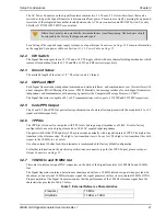
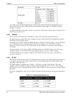
The Reset Command allows the Signal Generator to be put into a reset state when operational. When this command
is received, the Signal Generator performs the actions as shown in
. There are no data fields
associated with this command.
5.1.3.6
Watchdog Timer
The watchdog performs a Signal Generator board reset if it is not serviced for 3 seconds due to a software failure.
The software services the watchdog as frequently as possible to prevent the watchdog from resetting the digital
board under normal operating conditions.
Byte[31] – LS Byte
Byte[32]
Byte[33] – MS Byte
D7 – D0
D15 – D8
D23 – D16
7
6
5
4
3
2
1
0
15 14 13 12 11 10 9
8
23 22 21 20 19 18 17 16
D0 = LSB
D23 = MSB
n
n+1
n+2
f
n
f
n
+
f
n
f
n
+2
f
n
f
n
+3
f
n
f
n+1
f
n +1
+
f
n+1
f
n+1
+2
f
n+1
f
n+1
+3
f
n +1
f
n+2


