12
WAAS GUS Signal Generator User Guide Rev 1
Chapter 1
Introduction
Figure 1: WAAS GUS Signal Generator System Overview
Reference
Description
Reference
Description
1
RFU antenna
11
L1/L5 IF signals
2
GEO satellite
12
L1 GPS, L2 GPS, L1 GEO, L5 GEO
3
RF Upconverter and Power Amplifier
13
L1/L5 RF loop back from satellite
4
WAAS GUS Signal Generator
14
RF Switch
5
Receiver (WAAS G-III)
15
L-Band Filter and Low Noise Amplifier
6
RS-485 message input from CMP
16
L1 and L5 at L2 SIGGEN RF loop
7
RS-232 command input from WMP
17
L1 and L5 TLT
8
GPS antenna
18
L1 and L5 GEO or TLT
9
Test loop translator
19
Power combiner/splitter
10
C1/C5 uplink
shows a high level implementation of a WAAS GUS setup (see
Chapter 2, Minimum Connections on
Chapter 3, Setup Considerations on Page 19
, for more information on this topic).
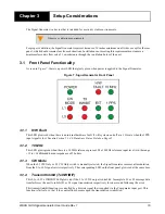
shows the
Signal Generator Front.


