Messages
Chapter 5
WAAS GUS Signal Generator User Guide Rev 1
27
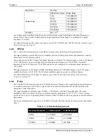
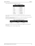
Table 8: L1/L5 Indication Field
Table 9: L1/L5 Indication Bit Field
5.1.3
Command Message
shows the command message fields. The sections that follow indicate the data fields for all valid command
message identifiers.
Table 10: Command Message Fields
5.1.3.1
Command Message Identifier Field
The Command Message Identifier field consists of one byte containing the command (instruction) message ID.
Based on this ID, the Signal Generator knows which data fields to interpret and what command needs to be
executed.
shows the Command Message Identifier byte field and bit order.
Command Message Identifier bit fields.
Field
Bytes
Byte
Position
L1/L5
Destination
WMP Destination
2
1
Byte [4:4]
L1=1, L5=5
1=L1, L5=5
Byte [4]
D7
D6
D5
D4
D3
D2
D1
D0
MSB
LSB
Field
Bytes
Byte Position
Description
3-1
1
Byte [5:5]
Command Message Identifier Field
3-2
1
Byte [6:6]
Control Command Data Field
3-3
1
Byte [7:7]
Symbol Rate Field
3-4
1
Byte [8:8]
Sub-Chip Field
3-5
2
Byte [9:10]
Code Chip Advance Field
3-6
2
Byte [11:12]
Symbol Advance Field
3-7
2
Byte [13:14]
L1 I coder init G2 Field or
L5 I coder init XB(I) Field
3-8
2
Byte [15:16]
L1 Q coder init G2 Field or
L5 Q coder init XB(Q) Field
3-9
6
Byte [17:22]
Code Chip Rate Field
3-10
2
Byte [23:24]
Code Chip Rate Ramp Field
3-11
6
Byte [25:30]
Carrier Frequency Field
3-12
3
Byte [31:33]
Carrier Frequency Ramp Field


