Setup Considerations
Chapter 3
WAAS GUS Signal Generator User Guide Rev 1
21
The AC Power Connector on the Signal Generator contains two 5 x 20 mm, 2.5 A slow-blow fuses that can be
serviced as long as the Signal Generator is disconnected from power. Fuses are accessed by pressing the upper and
lower tabs of the integrated fuse holder located between the AC Power connector and ON/OFF Switch. Use only
Littelfuse ® P/N 021802.5MXP or equivalent.
For a listing of the required input supply voltages, see
Input/Output Connectors on Page 52.
For more information
on the supplied 3-pin power cable, see
Section A.1.2.1, Power Cable on Page 55.
3.2.2
CW Switch
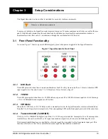
The Signal Generator provides a L1 CW and a L5 CW toggle switch with a mechanical latching mechanism which
remove all modulation from the L1 IF and RF or L5 IF and RF carriers respectively.
3.2.3
Ground Screw
The available length of the stud is 3/8”. The stud is an 8-32 thread.
3.2.4
CMP and WMP
Each Signal Generator has independent command and status interfaces, and communicates over this interface with
a host computer (WAAS Message Processor - WMP). Similarly, the message interface for each Signal Generator is
independent, and communicates with a message generator (the Comparator Message Processor - CMP).
The Signal Generator is capable of L1 or L5 communications via two ports, L1 WMP and L5 WMP respectively.
3.2.5
Code PPS Output
The L1 and L5 Code PPS Out ports allow synchronization of external test equipment with the modulated L1 or L5
signal available respectively.
3.2.6
1PPS In
The 1PPS level is an active low pulse with TTL levels driving an input impedance of 3 k
.. It is also factory
configurable to use active high pulses and/or a 50
AC coupled input impedance.
The pulse width of the 1PPS update is 200 microseconds nominally with a repetition rate of 1PPS. The high to low
transition is the reference edge. The high to low transition time is 5 ns or less. The high to low transition jitter with
respect to the 10 MHz is 1 ns or less.
Use of an external 50 ohm feed-thru terminator is recommended for factory default configuration.
For further information on the electrical specifications or connector type for the 1PPS In port, please see
on
Page 52.
3.2.7
10 MHz In and 10 MHz Out
There are two reference signal TNC connectors on the back of the Signal Generator for 10 MHz In and 10 MHz
Out.
The Signal Generator contains a detection mechanism and will use a 10 MHz reference signal when provided. In
the absence of an external 10 MHz reference signal, the signal generator will use its own internal 10 MHz OCXO.
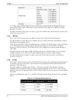
Proper operation of the Signal Generator requires that the performance of the 10 MHz reference signal have the
characteristics provided in
below.
Table 1: External Reference Characteristics
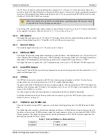
Blown fuses usually indicate that the internal hardware is malfunctioning. The hardware should
be returned to the factory for diagnosis and repair.
Frequency
10 MHz
Amplitude
13 dBm ± 1 dBm


