Minimum Connections
Chapter 2
WAAS GUS Signal Generator User Guide Rev 1
17
An example configuration would result from the following steps (see also
):
1. Place the Signal Generator on a suitable work surface.
2. Connect the 1PPS In port on the Signal Generator to the 1PPS Out port on the Receiver with
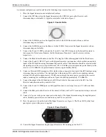
interconnecting coaxial cable. A typical coaxial cable is shown in
.
Figure 5: Coaxial Cable
3. Connect the 10 MHz In port on the Signal Generator to the 10 MHz external reference with an
interconnecting coaxial cable.
4. Connect the 10 MHz In port on the Receiver to the 10 MHz Out port on the Signal Generator with an
interconnecting coaxial cable.
5. Connect the L1 and L5 CMP ports and the L1 and L5 Code 1PPS Out ports on the Signal Generator to
their respective Data Source Modules. Set the Data Source Modules L1 and L5 selector switches
respectively.
6. Connect the Data Source Modules to the Test PC using the USB cables supplied with the Data Source.
7. Connect the L1 and L5 RF OUT ports on the Signal Generator to attenuators which are then connected to
inputs of the RF Combiner using interconnecting coaxial cables. The attenuators should be selected so that
the signal power at the receiver input is between -105 to -90 dBm given an input noise power density to the
receiver of -150 dBm/Hz. (Typical attenuator vales are approximately 50dB.)
8. Connect a Powered GPS Antenna to a LNA which is then connected to the input of the RF Combiner using
interconnecting coaxial cables. The total gain due to the antenna LNA, cable losses, combiner and any
external LNA should be approxi20 dB or equivalently the noise power provided at the receiver
input, accounting for cascaded gain and noise figure, should be approximately -150 dBm/Hz.
9. Connect the output of the RF Combiner to a DC Block which is then connected to the RF1 In of the
Receiver using interconnecting coaxial cables.
10. Connect the L1 and L5 WMP ports on the Signal Generator to a serial port on your PC with serial data
cables.
11. Connect the Data port on the Receiver to the same LAN that your Test PC is connected to using a network
cable.
12. Connect AC power to the power input port on the back of the Signal Generator using the supplied power
cable. Similarly, power the receiver and ensure your PCs are powered.
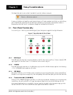
13. Press the power switch on the back of the Signal Generator, see
. The Power LED on the front
panel glows green while power is applied.
Figure 6: Power Switch
14. Control the Signal Generator using the Signal Generator GUI running on the Test PC.


