7. Replacement
Parts.
Note
It is recommended that only suitably competent persons are
allowed to undertake replacement of parts.
7.1
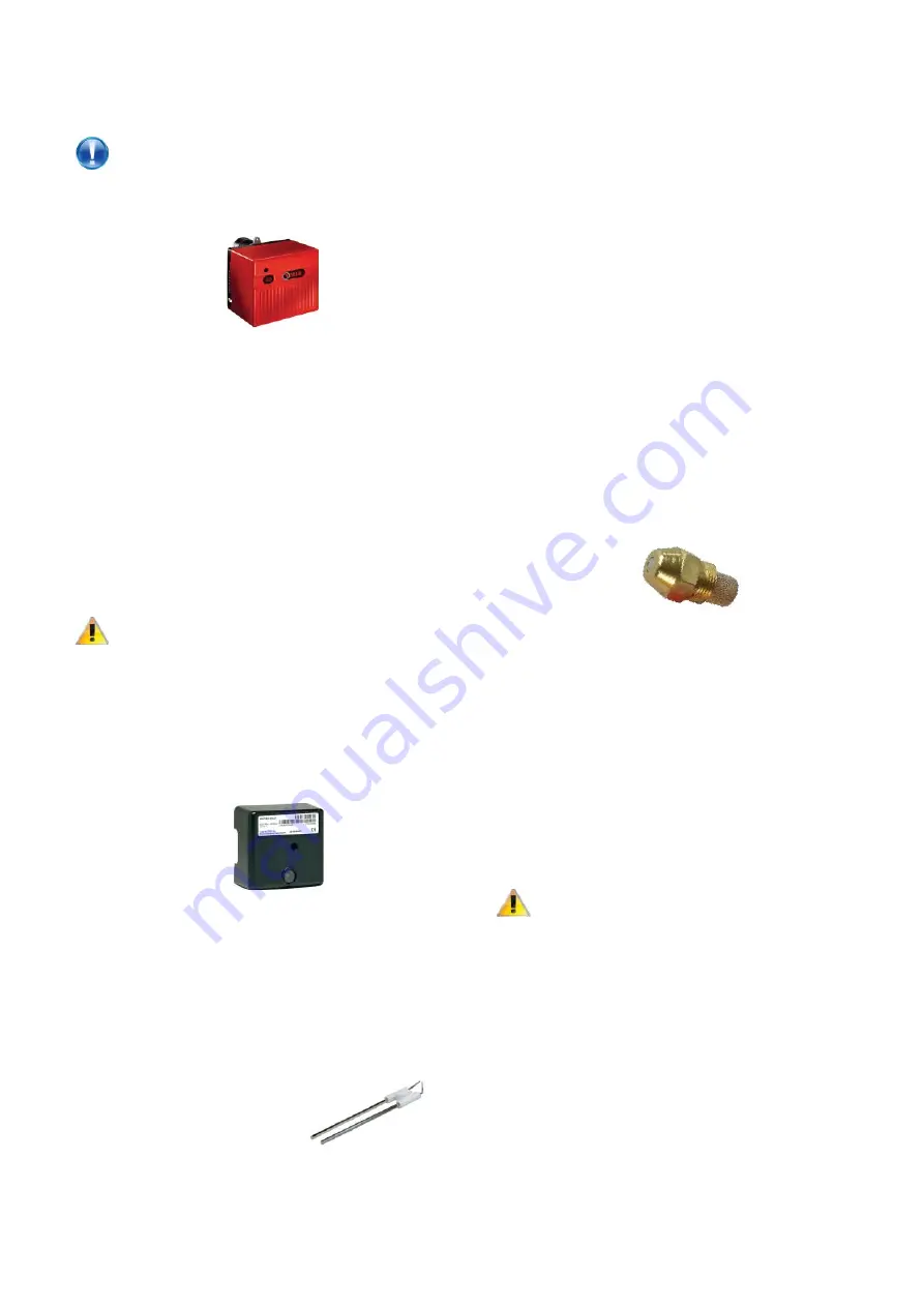
Burner.
•
Disconnect electrical supply to the heater and shut off
oil supply.
•
Disconnect fuel line.
•
Detach electrical connections via plugs.
R40 series:
•
Using an 13mm spanner, remove the nut holding the
unit to the burner fl ange.
•
Withdraw the burner from the throat of the heat
exchanger.
RL34/44 series:
•
Using a 6mm Allen key, remove the bolt holding the
burner to the fl ange.
•
Pull the burner forward on the two supporting bars.
C
aution - Heavy!
•
Remove the two supporting bar bolts and carefully
remove the burner through the throat of the fl ange.
•
Replace in reverse order.
7.2
Controller
•
Disconnect electrical supply to the heater.
•
Remove the burner cover.
•
Remove the screw fi xing the controller to the base
and withdraw controller.
•
Replace in reverse order.
7.3
Electrode Assembly
•
Disconnect electrical supply to the heater.
•
Remove the burner cover.
R40 series:
•
Using an 13mm spanner, remove the nut holding the
unit to the burner fl ange.
•
Withdraw the burner from the throat of the heat
exchanger, support on bracket/fl ange lugs.
•
Remove the fi xing screw(s) holding the End Cone and
withdraw from burner head.
•
Loosen the screw clamping the electrodes.
RL34/44 series:
•
Using a 6mm Allen key, remove the bolt holding the
burner to the fl ange.
•
Pull the burner forward on the two supporting bars.
•
Loosen the screw clamping the electrodes.
•
Withdraw electrodes forward and away from the
burner.
•
Replace in reverse order.
7.4 Nozzle
•
Disconnect electrical supply.
R40 series:
•
Using an 13mm spanner, remove the nut holding the
unit to the burner fl ange.
•
Withdraw the burner from the throat of the heat
exchanger.
•
Remove the fi xing screw(s) holding the End Cone and
withdraw from burner head.
RL34/44 series:
•
Using a 6mm Allen key, remove the bolt holding the
burner to the fl ange.
•
Pull the burner forward on the two supporting bars.
C
aution - Heavy!
•
Remove the two supporting bar bolts and carefully
remove the burner through the throat of the fl ange and
place on fl at surface.
•
Remove the fi xing screw(s) holding the End Cone and
withdraw from burner head.
•
Remove the fi xing screw(s) holding the inner Cone
and withdraw from burner head.
•
Remove the fi xing screw(s) holding the Diff user Disc
Assembly and remove from burner head.
•
Using a 17mm spanner, remove the nozzle
•
Replace in reverse order.
Summary of Contents for Reznor 120
Page 28: ...Wiring Diagram 20 45 600 30 40 ON OFF Riello Burner Integral SC SZ 230 50 1ph...
Page 29: ...Wiring Diagram 20 45 601 60 85 ON OFF Riello Burner Integral SC SZ 230 50 1ph...
Page 30: ...Wiring Diagram 20 45 602 120 135 ON OFF Riello Burner Integral SC SZ 230 50 1ph...
Page 31: ...Wiring Diagram 20 45 603 60 300 ON OFF Riello Burner Integral SC SZ 415 50 3ph...
Page 32: ...Wiring Diagram 20 45 616 30 40 ON OFF Riello Burner Remote SC SZ 230 50 1ph...
Page 33: ...Wiring Diagram 20 45 617 60 85 ON OFF Riello Burner Remote SC SZ 230 50 1ph...
Page 34: ...Wiring Diagram 20 45 618 120 135 ON OFF Riello Burner Remote SC SZ 230 50 1ph...
Page 35: ...Wiring Diagram 20 45 619 60 300 ON OFF Riello Burner Remote SC SZ 415 50 3ph...
Page 36: ...Wiring Diagram 20 45 604 30 40 ON OFF Riello Burner Integral CP4 230 50 1ph...
Page 37: ...Wiring Diagram 20 45 605 60 85 ON OFF Riello Burner Integral CP4 230 50 1ph...
Page 38: ...Wiring Diagram 20 45 606 120 135 ON OFF Riello Burner Integral CP4 230 50 1ph...
Page 39: ...Wiring Diagram 20 45 607 60 300 ON OFF Riello Burner Integral CP4 415 50 3ph...
Page 40: ...Wiring Diagram 20 45 620 30 40 ON OFF Riello Burner Remote CP4 230 50 1ph...
Page 41: ...Wiring Diagram 20 45 621 60 85 ON OFF Riello Burner Remote CP4 230 50 1ph...
Page 42: ...Wiring Diagram 20 45 622 120 135 ON OFF Riello Burner Remote CP4 230 50 1ph...
Page 43: ...Wiring Diagram 20 45 623 60 300 ON OFF Riello Burner Remote CP4 415 50 3ph...
Page 44: ...Wiring Diagram 20 45 612 30 40 ON OFF Riello Burner No Controls 230 50 1ph...
Page 45: ...Wiring Diagram 20 45 613 60 85 ON OFF Riello Burner No Controls 230 50 1ph...
Page 46: ...Wiring Diagram 20 45 614 120 135 ON OFF Riello Burner No Controls 230 50 1ph...
Page 47: ...Wiring Diagram 20 45 615 60 300 ON OFF Riello Burner No Controls 415 50 3ph...
Page 55: ...5 Parts Lists...
Page 66: ...Notes...
Page 67: ...Notes...


