background image

3-2                                                                                                                                            MAR 2016 49457610 TRIPP HD RevB

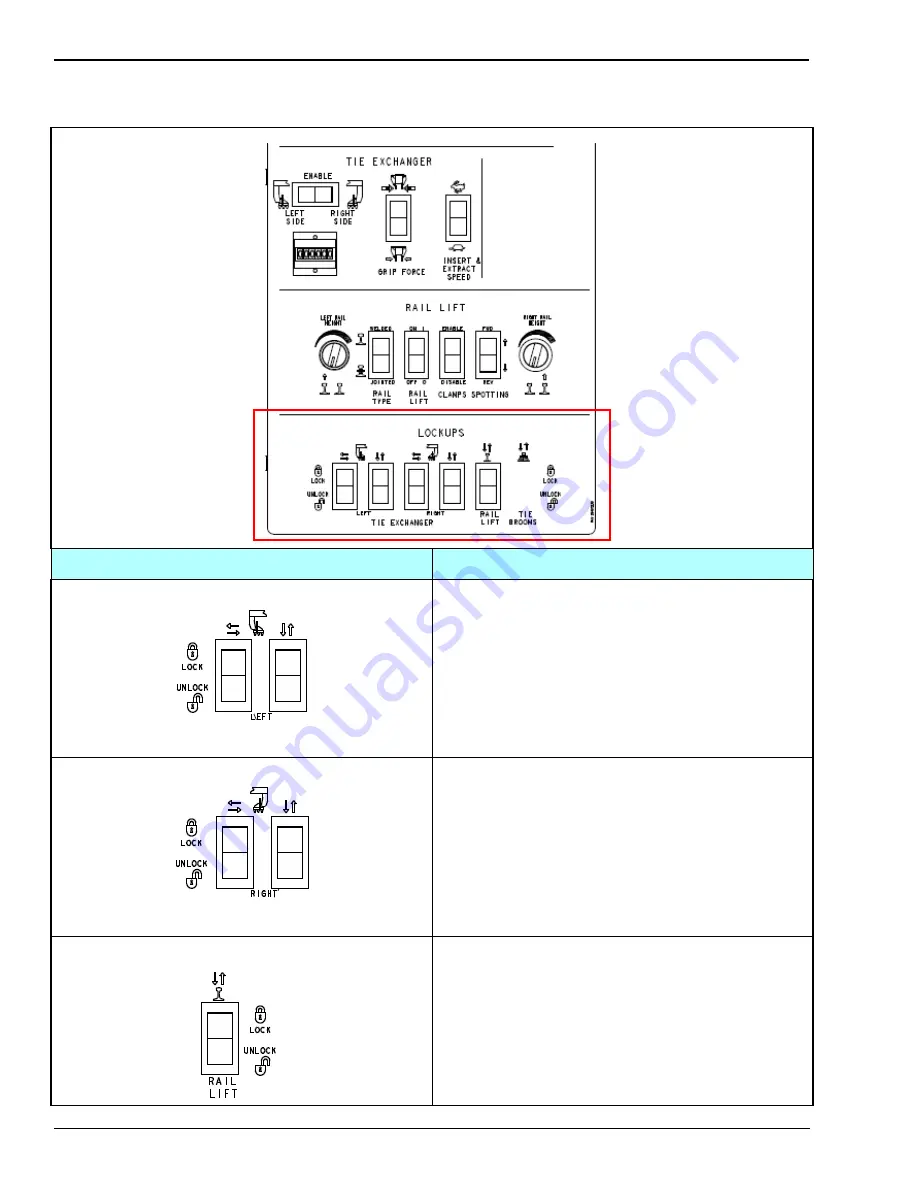
LOCKUPS

LOCKUP CONTROLS

CONTROL

DESCRIPTION

Left Tie Exchanger Lock and Unlock Switches

Located on the left side of the lock/unlock console, 
these switches control the pneumatic locks on the left 
side tie exchanger.  One switch controls the up/down 
movement; the other switch controls lateral movement.
LOCK: Controls the pneumatic cylinders to place the 
mechanical locks on the hydraulic cylinders of the left 
side.
UNLOCK: Controls the pneumatic cylinders to release 
the mechanical locks on the hydraulic cylinders.

Right Tie Exchanger Lock and Unlock Switches

Located on the center of the lock/unlock console, these 
switches control the pneumatic locks on the right side 
tie exchanger.  One switch controls the up/down 
movement; the other switch controls lateral movement.
LOCK: Controls the pneumatic cylinders to place the 
mechanical locks on the hydraulic cylinders on the 
right side.
UNLOCK: Controls the pneumatic cylinders to release 
the mechanical locks on the hydraulic cylinders.

Rail Lift Workhead Lock and Unlock Switches

Located on the right side of the lock/unlock console, 
this switch controls the pneumatic locks on the rail lift 
hydraulic cylinders.
LOCK: Controls the pneumatic cylinders to place 
mechanical locks on the hydraulic lift cylinders.
UNLOCK: Controls the pneumatic cylinders to release 
the mechanical locks on the hydraulic cylinders.

Summary of Contents for TRIPP HD

Page 1: ...Operation Manual Including Routine Maintenance Reorder Manual P N 49457607 March 2016 Starting Machine S N 760700 Revision RevB TRIPP Model HD...

Page 2: ...REVISION HISTORY Release Rev Date Change Description Rev A June 2015 Initial manual version for TRIPP HD Rev B March 2016 Added information for Cummins Tier 4 engine...

Page 3: ...can be found at the back of this manual behind the tab marked Component Data This manual is broken down into sections which have been separated by index tabs Mechanical Tab has individual parts break...

Page 4: ...cost through the Nordco Part Sales Department Additional service information parts and application information is also available through the below Nordco product support resources Nordco Sales Oak Cr...

Page 5: ...erial contained in this machine If you are interested in receiving this information please refer to the Name model and Serial Number of your machine when calling or writing and direct your inquiries t...

Page 6: ......

Page 7: ...ALERTS 1 4 SAFETY PROCEDURES 1 5 SAFETY FEATURES 1 6 ENGINE SAFETY FEATURES 1 6 LOCKUPS 1 6 SPRING PARKING BRAKES 1 6 STEPS PLATFORMS AND HAND RAILS 1 6 SAFETY DECALS ON THIS MACHINE 1 7 2 LOGOUT TAG...

Page 8: ...5 18 6 MACHINE OPERATION STARTUP 6 1 PRE START UP CHECKS 6 1 STARTING THE ENGINE 6 1 TRAVEL MODE 6 2 FORWARD RAILWAY TRAVEL 6 2 REVERSE RAILWAY TRAVEL 6 2 WORK MODE 6 3 RAIL LIFT OPERATION 6 3 TIE EX...

Page 9: ...HEDULE 7 12 DETAILED WEEKLY INSTRUCTIONS 7 12 MONTHLY SCHEDULE 7 14 DETAILED MONTHLY INSTRUCTIONS 7 14 QUARTERLY SCHEDULE 7 18 DETAILED QUARTERLY INSTRUCTIONS 7 18 YEARLY SCHEDULE 7 19 DETAILED YEARLY...

Page 10: ...Contents 4 MAR 2016 49457607 HD TRIPP RevB TABLE OF CONTENTS...

Page 11: ...rdous situation which if not avoided COULD result in death or serious injury CAUTION CAUTION indicates a potentially hazardous situation which if not avoided MAY result in minor or moderate injury and...

Page 12: ...empting to operate this machine Use the PRE START UP CHECKS on page 6 1 to check the machine for obvious faults Repair and or replace components as necessary PRIOR to operating the machine Before clim...

Page 13: ...ETY WHILE STARTING THE MACHINE Nordco recommends the use of a Command position This means that the machine is never running unless someone is at or near the main operator control station To prevent in...

Page 14: ...mprise the integrity of this machine 8 There are welding cautions on this machine Pay attention to them PRIOR to welding 9 Kits supplied by Nordco have welding instructions included Welding of any com...

Page 15: ...1 Figure 1 1 7 Place a TAGOUT card on the switch after you have switched the BDS to the OFF position 8 Place a LOCKOUT lock on the switch after you have switched it to the OFF position 9 Bleed off th...

Page 16: ...orkheads See MACHINE LOCKUPS on page 3 1 SPRING PARKING BRAKES The Spring Parking Control Brake Air Deactivated will not release if the air pressure in the braking system is less than 60 PSI When rele...

Page 17: ...dered from the Parts Sales Department See Table 1 1 for a list of Decals on this Machine Table 1 1 Safety Decals on this Machine PART NUMBER DESCRIPTION LOCATION 5642 0001 General Machine Cautions Ins...

Page 18: ...1 8 MAR 2016 49457607 TRIPP HD RevB SAFETY INSTRUCTIONS AND INFORMATION...

Page 19: ...G BRAKE button located on the center control console NOTE Apply this button to release air pressure that normally releases the parking brakes By relieving this pressure a high energy spring applies to...

Page 20: ...this machine IMPORTANT Nordco cannot be held responsible for injury caused by failure to comply with your company s Lockout Tagout Procedures ONLY qualified and trained personnel are to install Logou...

Page 21: ...electrical power supply to the machine and prevents accidental startup of the engine while servicing All Hydraulic Systems Hydraulic Pressure WARNING After Lockout Tagout and BEFORE any repair or main...

Page 22: ...ry lockup key located on the proximity flag bracket on the side of the workhead is then inserted into the hole on the top of the hammer side plate NOTE This cuts off hydraulic pressure or flow to the...

Page 23: ...ge There are several areas throughout the machine designated as lockup points for location areas See Figures 3 1 3 2 and 3 3 Duplicate lockups are provided on both sides of the machine Lockup points h...

Page 24: ...Located on the center of the lock unlock console these switches control the pneumatic locks on the right side tie exchanger One switch controls the up down movement the other switch controls lateral m...

Page 25: ...g operations This machine is equipped with hydraulically operated lockups These lockups are engaged locked or disengaged unlocked using pushbuttons on the operator control panel To engage the lockups...

Page 26: ...3 4 MAR 2016 49457610 TRIPP HD RevB LOCKUPS...

Page 27: ...one Tie Exchanger Extended 11 Feet 10 3 4 inches 3 6 Meters Height 11 Feet 6 1 2 inches 3 5 Meters Travel Speed Maximum 23 mph 37 km h Rated Draw Bar Pull on rail 1000 lbs 454 kg Wheel Base 27 Feet 3...

Page 28: ...n total system 17 6 Quarts 16 7 liters Oil Capacity with Suspended Oil Pan total system 20 8 Quarts 19 7 liters Oil Capacity with High Capacity Oil Pan total system 27 9 Quarts 26 4 liters Coolant Cap...

Page 29: ...is manual are subject to change No part of this manual may be reproduced in any form or by any means without our written permission PNEUMATIC SYSTEM Engine Mounted Compressor Unloading Valve Relief Va...

Page 30: ...4 4 MAR 2016 49457610 TRIPP HD RevB GENERAL MACHINE SPECIFICATIONS OVERALL MACHINE PHYSICAL DIMENSIONS See Figure 4 1 Figure 4 1 MACHINE DIMENSIONAL INFORMATION...

Page 31: ...GENERAL MACHINE SPECIFICATIONS MAR 2016 49457610 TRIPP HD RevB 4 5 RAILWAY LINE CLEARANCE Figure 4 2...

Page 32: ...4 6 MAR 2016 49457610 TRIPP HD RevB GENERAL MACHINE SPECIFICATIONS...

Page 33: ...either side of the machine Workheads and propulsion operation is done through a series of hydraulic valves located either remotely or at a manifold NOTICE During operation of the tie exchanger either...

Page 34: ...YSTEM FAMILIARIZATION OPERATORS CENTER CONSOLE Shown here is the diagram of the operators center console See Figure 5 1 The center console is then detailed in additional following figures See Figures...

Page 35: ...egen for both the Murphy Gauge and Controls Inc Gauge used On the JD Tier 4 Engines Refer to Section 4 Maintenance and the JD Engine Manual for More Detailed Information EMERGENCY STOP Press this butt...

Page 36: ...es the use of the brake pedal in order to apply brakes TRAVEL WORK Two position switch TRAVEL WORK TRAVEL Raises retracts workheads to allow insertion of lockups inflates air springs disables hand con...

Page 37: ...nings and 30 seconds on shutdown conditions This is NOT recommended for use on machines with Tier 4 engines that have reached a derate stage Check the alarm condition first before using the silence mo...

Page 38: ...able 5 2 LOWER CENTER CONSOLE SYMBOL CONTROL DESCRIPTION TIE EXCHANGER CONTROLS ENABLE LEFT RIGHT SIDE This switch is used to select either the left or right tie exchanger arm for operation Position o...

Page 39: ...es the voltage required from the magnetic sensors on the rail lift workhead sensor rods to set the height of rail lift RAIL TYPE Located on the left side of the rail lift console this switch selects t...

Page 40: ...unlock console these switches control the pneumatic locks on the right side tie exchanger One switch controls the up down movement the other switch controls lateral movement LOCK Controls the pneumat...

Page 41: ...ion and setup instructions LED LIGHTS OUTER BEZEL OF POWERVIEW LED status lights are located on the upper left and upper right sides of the PowerView When they are lit the screen will tell you the fau...

Page 42: ...middle and at the status that is showing a fault the oil pressure Remember the screen shows NEXT or MORE if more than one error has occurred Scroll through the screen until you find the individual co...

Page 43: ...OPERATOR SYSTEM FAMILIARIZATION MAR 2016 49457610 TRIPP HD RevB 5 11 Figure 5 4 Regen Control Gauge...

Page 44: ...in until the regen is completed The equipment operates normally and no actions need to be taken Operate the machine as normal IMPORTANT If operating in an area where high exhaust temperatures 1022 F m...

Page 45: ...service regen taking 3 4 hours will have to be done by an authorized John Deere Service tech Contact a local John Deere Servicing Dealer SCREEN EXAMPLES IF YOU SEE THIS IT MEANS You need to run a REGE...

Page 46: ...ield wipers operator cab climate control and emergency pump operation Condition indicators for the hydraulic filters and temperature fuel tank levels and a speedometer displaying machine travel speed...

Page 47: ...dicated alarm sounds when the temperature is out of the operational range or the oil level is low FUEL Level Gauge Displays the total available fuel contained in the fuel tank Speedometer RPM KPM Odom...

Page 48: ...ht up Backup alarm sounds during reverse travel REVERSE Travel When this is selected the rear locomotive lights light up Backup alarm sounds during forward travel LOWER Wiper Switch UPPER Wiper Switch...

Page 49: ...loses the tie grippers onto the tie with the preset force as set by the pots on the right hand control panel buttons 1 and 2 are one rocker switch 3 Rail Lift Cycle Set Reset Sets and resets the autom...

Page 50: ...t Left Side Enabled Left movement tilts gripper head up right movement tilts gripper down Right Side Enabled Left movement tilts gripper head down right movement tilts gripper head up Figure 5 8 Left...

Page 51: ...oystick Controls the tilt of the workhead jaws to assist in maneuvering rail ties RAIL LIFT JOG DOWN Button Option not show Control lifts both rails simultaneously The height of lift is set by the pot...

Page 52: ...5 20 MAR 2016 49457610 TRIPP HD RevB OPERATOR SYSTEM FAMILIARIZATION...

Page 53: ...the PowerView to come on c When the PowerView screen comes on a WAIT TO START PREHEAT message appears on the screen 5 When the message disappears and the light goes out it is OK to start the engine On...

Page 54: ...witch Retracts the hydraulic cylinders for the rail lift workhead Inflates the air springs Disables the hand controller 10 Place the TRAVEL switch in the FORWARD position 11 Press down on the forward...

Page 55: ...SET RESET button to ensure the height adjustment b Temporarily Use the manual LH RAIL LIFT and RH RAIL LIFT switche s to lift the rail s if the tie exchanger needs to clear an object during tie remov...

Page 56: ...eels 4 Remove the T bolt from the back side of the air canister and insert it into the bottom of the brake canister 5 Tighten the T bolt until the brakes release The spring inside of the canister comp...

Page 57: ...Place the TIE EXCHANGER LOCK UNLOCK switches to the LOCK position Use the joystick to ensure the locks are fully engaged 3 Press the RAIL LIFT CYCLE SET RESET button on the joystick as needed to ensu...

Page 58: ...er to the HYDRAULIC Tabbed Preface section later in this publication for instructions EMERGENCY STOP There are two EMERGENCY STOP controls One is located on the center operator s console One is locate...

Page 59: ...s machine See LOGOUT TAGOUT on page 2 1 DO NOT start the engine if repairs or work is being performed alone You should always have at least two people working together if the engine must be run during...

Page 60: ...7 2 MAR 2016 49457610 TRIPP HD RevB ROUTINE MAINTENANCE Figure 7 1 RAIL CLAMP LUBE CHART...

Page 61: ...ROUTINE MAINTENANCE MAR 2016 49457610 TRIPP HD RevB 7 3 Figure 7 2 SUSPENSION BRAKES PROPULSION LUBE CHART...

Page 62: ...7 4 MAR 2016 49457610 TRIPP HD RevB ROUTINE MAINTENANCE Figure 7 3 TIE EXCHANGER LUBE CHART...

Page 63: ...Gauge Fill as required D9 Check Hydraulic Oil Filter Indicators at Front Control Panel requires machine running and working D10 Inspect Hoses and Fittings for Leaks D11 Reserved for Future Use D12 Re...

Page 64: ...additional oil until the oil level is BELOW the crosshatch marks B on the dipstick See DIESEL ENGINE OIL in Fuels Lubricants and Coolant Section for oil specifications Depending on the application oil...

Page 65: ...tem for leaks A Radiator Filler Neck Cap B Radiator Figure 7 5 D5 ENGINE Check Fuel Filter NOTE The engine is equipped with a water in fuel sensor at the fuel filter An indicator light signals to the...

Page 66: ...ound Inspection Make a thorough walk around inspection of the engine compartment Look for oil or coolant leaks worn fan and accessory drive belts loose connections and trash buildup Remove trash build...

Page 67: ...on the center console to provide a visual display of filter cleanliness Units are equipped with an additional Main Pump Pressure Filter and a filter indicator box that gives the operator a visual sta...

Page 68: ...by reading the sight gauge on the side of the reservoir Use only Diesel fuel D27 MISCELLANEOUS Inspect for Tight Electrical Connections Harnesses Daily inspection of the harnesses connected to the co...

Page 69: ...ttings are located on the underside of the pillow blocks Remote wheel bearing grease fittings for the wheels are located on the outside of the suspension arm Weather conditions affect the time interva...

Page 70: ...ns Follow LOC ITEM SYM TASK MISCELLANEOUS W1 Perform all Daily Lubrication and Maintenance Procedures W2 Check Battery Condition W3 Check Tautness of and Oil Propulsion Chains W4 Oil Propulsion Chain...

Page 71: ...ghtness has been reached tighten the adjusting screw locknut 5 Drizzle engine oil along the chain and sprockets top and bottom 6 Oil the propulsion chain adjusting nuts 7 Reinstall the chain guard W7...

Page 72: ...ould be neither too tight nor too loose Belts that are too tight impose excess load on the crankshaft fan and or alternator bearings shortening both belt and bearing life Excessively overtightened bel...

Page 73: ...ease and secure the spring Repeat for all brake shoes that need replacing 5 Remove the cotter pin on pin C and remove pin C in brake lever and brake shoe bracket 6 The brake shoe and bracket can now b...

Page 74: ...ease in addition to the air Repeat for all brake shoes that need replacing 8 Turn IGNITION switch to the OFF position this will reset the parking brake button but the canisters will remain released be...

Page 75: ...replaced and brake canister release bolts have been removed select the DEADMAN mode from the SERVICE DEADMAN switch 21 Set the parking brake by pulling out the yellow PARKING BRAKE button on most mod...

Page 76: ...Take precautions to prevent moisture contamination Change fluid whenever contamination occurs because even small amounts of water can affect system performance as well as induce corrosion and oil bre...

Page 77: ...r s Manual in Component Data More Detailed Instructions Follow LOC ITEM SYM TASK MISCELLANEOUS Y1 Perform all Daily Weekly Monthly and Quarterly Lubrication and Maintenance Procedures Y2 Steam Clean E...

Page 78: ...below the expected lowest ambient temperature Fuel lubricity should pass a maximum scar diameter of 0 45 mm as measured by ASTM D6079 or ISO 121561 Sulfur Content for Interim Tier 4 and EU Stage IIIB...

Page 79: ...ROUTINE MAINTENANCE MAR 2016 49457610 TRIPP HD RevB 7 21 CATERPILLAR ENGINE FAULT CODES Shown here are normal Caterpillar engine fault codes Figure 7 23 Caterpillar Engine Fault Codes Page 1...

Page 80: ...7 22 MAR 2016 49457610 TRIPP HD RevB ROUTINE MAINTENANCE Figure 7 24 Caterpillar Engine Fault Codes Page 2...

Page 81: ...ROUTINE MAINTENANCE MAR 2016 49457610 TRIPP HD RevB 7 23 Figure 7 25 Caterpillar Engine Fault Codes Page 3...

Page 82: ...7 24 MAR 2016 49457610 TRIPP HD RevB ROUTINE MAINTENANCE...

Reviews: