17
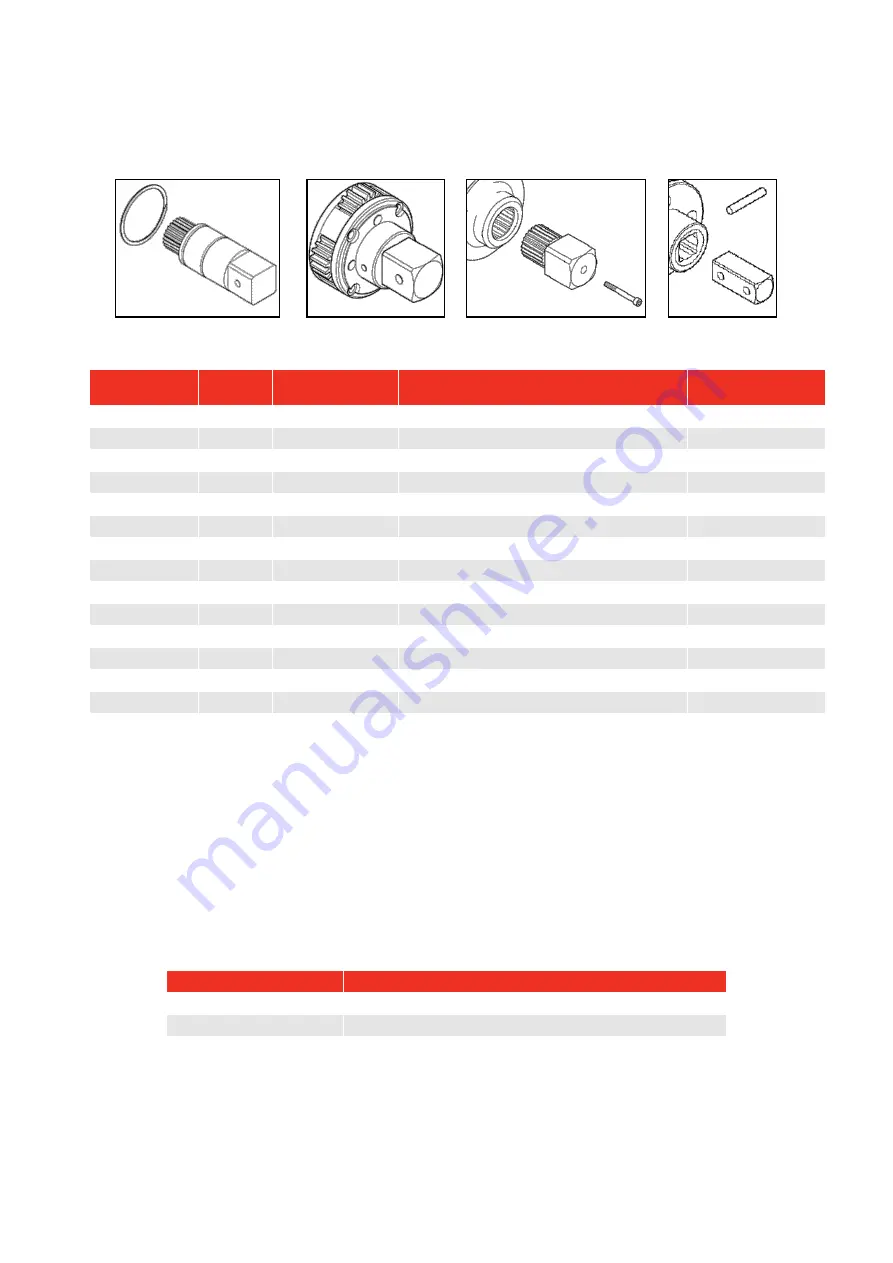
Drive Square
To avoid internal damage (especially due to torque overload), the output drive square has been designed to
shear first. This saves major internal damage and allows easy square removal.
FIGURE 13 –
Drive square fixing (left to right): Pin, Carrier Assembly, Screw and circlip.
Tool
Square
Size
Drive Square
Part Number
Fixing
Screw Torque
(N∙m)
PT 1 / PT 2
¾”
# 16424
Pin (# 26228)
-
PT 1 / PT 2
1”
# 16425
Pin (# 26228)
-
PT 5
1”
# 16549
Pin (#26242)
-
PT 6
1 ½”
# 16548
Carrier assembly.
-
PT 7
1 ½”
# 16295
M5 screw (# 25352.45)
8 – 9
PT 9
1 ½”
# 16611
M5 screw (# 25352.40)
8 – 9
PT 11
2 ½”
# 16323
M6 screw (# 25353.60)
16 – 18
PT 12
2 ½”
# 16310
M6 screw (# 25353.60) + Circlip (# 26432)
16 – 18
PT 13
2 ½”
# 16310
M6 screw (# 25353.60) + Circlip (# 26432)
16 – 18
PT 14
3 ½”
# 16309
M6 screw (# 25353.60)
16 – 18
PT 15
-
-
Application specific
-
PT 16
-
-
Application specific
-
PT 17
-
-
Application specific
-
PT 18
-
-
Application specific
-
NOTE:
The drive squares are designed to be replaced by a competent service engineer with
standard tools. A new fixing screw is recommended on reassembly.
TIP: If the square has sheared it may be necessary to use pliers to remove the broken parts.
Cleaning
Keep the tool in a clean condition to aid safety. Do not use abrasives or solvent based cleaners.
Disposal
Recycling considerations:
Component
Material
Sleeve
Aluminium casting with epoxy finish.
Annulus
Alloy steel with nickel plate finish.
Reaction plate
Alloy steel with chemical black finish
Summary of Contents for 16011.X
Page 21: ...20...


