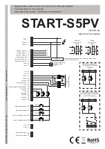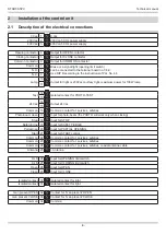
Foreword
This manual provides all the specific information you need to fa-
miliarize yourself with and correctly operate your unit.
Read it very carefully when you purchase the instrument and con-
sult it whenever you have doubts regarding use and before per-
forming any maintenance operations. The producer has the right
to modify the product without previous notice.
Environmental protection
measures
Information regarding the environment for customers
within the European Union. European Directive EC
2002/96 requires that units bearing this symbol on the
unit and/or on the packaging be disposed of separate-
ly from undifferentiated urban wastes.
The symbol indicates that the product must not be disposed of
with the normal household wastes. The owner is responsible for
disposing of this product and other electrical and electronic equip-
ment through specific waste collection facilities indicated by the
government or local public agencies. Correct disposal and recy-
cling help prevent any potentially negative impact on the environ-
ment and human
health. To receive more detailed information regarding disposal
of your unit, we recommend that you contact the competent pub-
lic agencies, the waste collection service or the shop where you
purchased the product.
1
Introduction
4
1.1
Safety precautions
1.2
Symbols and warning
1.3
Security system
1.4
Preliminary checks
1.5
Type of electrical wires
5
1.6
Type of installation
1.7
Connections Notes
2
Installation of the control unit
6
2.1
Description of the electrical connections
2.2
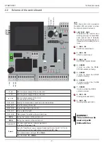
Scheme of the control board
7
2.3
Connection of the TENSION
8
2.4
Connection of the LAMP
2.5
Connection of a 24V light for working and opening gate
2.6
Connection of a CONTACTOR
2.7
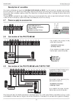
Power supply to accessories
9
2.8
Connection of the PHOTO-BEAM
2.9
Connection of the PHOTO-BEAM with PHOTO-TEST
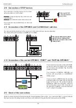
2.10
Connection of STOP devices
10
2.11
Connection of the OPENING
and CLOSING limit switches
2.12
Connection of the control OPENING “START”
and “PARTIAL OPENING”
2.13
Check of the connections
3
Functions and adjustment
11
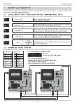
3.1
Set up of the START control
and PARTIAL OPENING of the DIP A
3.2
COMPASS function of DIPA
3.3
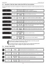
Resume of the functions with other DIP A micro-switches
12
3.4
Set up of the DIP B
4
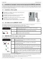
Installation of the plug-in receiver and managing
of the REMOTE CONTROL
13
4.1
Installation of the hybride
4.2
Cancellation of the MEMORY CODE
4.3
MEMORIZATION of a single remote control
5
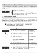
Turn on and program of the control unit
14
5.1
Working time memorization
5.2
Memorization of the working time
with the OPENING CONTROL “START”
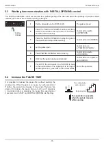
5.3
Working time memorization
with PARTIAL OPENING control
15
5.4
Increase the PAUSE TIME
6
Note
16
7
Declaration of CE conformity
17
Index
START-S5PV
Technical manual
-3-
Self-learning working time
4 functions (collective use included)
Set up with dip-switch
Isolated contact for light of opening gated
Radio decode supplied only for fixed standard codes from
12 to 64 bit and HCS rolling code.
Reduced dimensions
Partial opening with separate control
Connection of the photo-beams with TEST
Description of the product
Small legend
LSO or FCA
Open limit switch
LSC or FCC
Close limit switch
START
control to drive the gate
PEDESTRIAN
in sliding units: control partial opening
Vac
alternate current
Vdc
direct current
NC
normally closed
NO
normally open
Isolated contact
isolated from power supply

