INSTALLATION AND MAINTENANCE INSTRUCTIONS
MOS GB 1411-1PELLUX 100331139
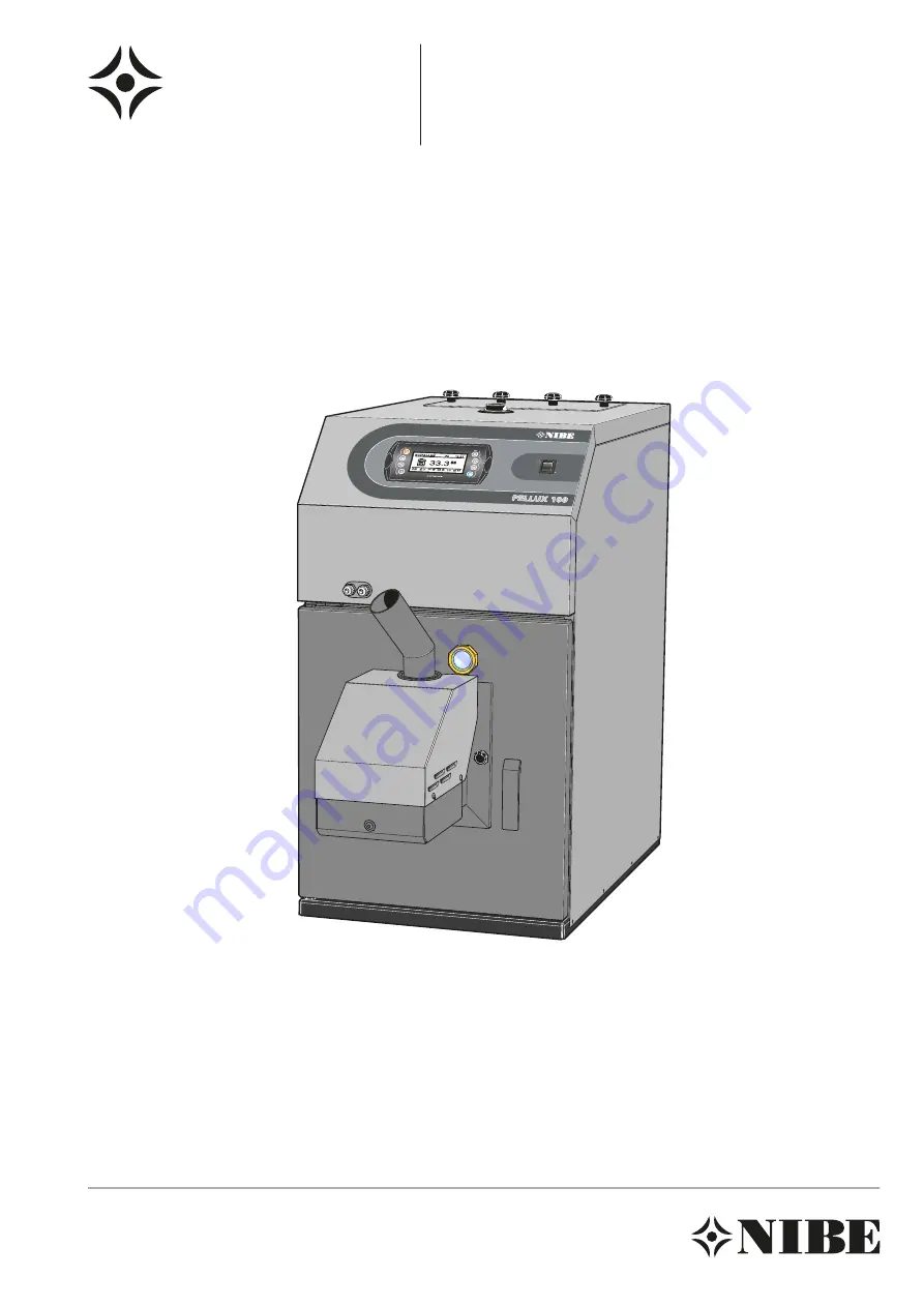
PELLUX 100
AP
H
Page 1: ...INSTALLATION AND MAINTENANCE INSTRUCTIONS MOS GB 1411 1 PELLUX 100 331139 PELLUX 100 APH...
Page 2: ......
Page 3: ...ns Electrical connections Connection 15 Internal fuse protection 15 Connecting the control computer 15 Connection burner 17 Connecting the outside sensor 17 Connection of flow sensor 17 External contr...
Page 4: ...offset setting On delivery 2 Make any changes to the default settings here Datum__________________________ Sign___________________________ The serial number is located on the left of the top of the ho...
Page 5: ...ped with a climate controlled automatic shunt Available output with pellet operation is 20 kW Heating The boiler water is led from the top of the boiler to the radiator circuit via a shunt valve where...
Page 6: ...ess the On Off button for a minimum of 3 seconds to start or switch off the control computer NOTE The boiler does not switch off It is only the control computer that is switched off Heating Allows pos...
Page 7: ...nd fuel supply increase gradually F At the end of the start up process the boiler switches to the set control program TIP Normal firing up takes approx 9 minutes If during this time the photocell does...
Page 8: ...aning the boiler Cleaning Settings of fuel volume for firing up start of the firing up sequence and fans Firing up When the fuel has been ignited and a flame can be detected the fuel volume is increas...
Page 9: ...hen you have found the menu that you wish to change or see sub menus in open it by pressing Enter Explanation Menu You can see the heat pump s present large digits and the set temperatures small digit...
Page 10: ...ng Program Time 1 Time heats the section in relation to the set time intervals 2 Permanent ensures that the section always maintains a comfortable temperature regardless of the set time intervals 3 Sw...
Page 11: ...temperature in the room and offsets the supply temperature If the temperature in the room exceeds or falls below the set value of the room sensor the temperature of the supply line is reduced re spec...
Page 12: ...ith automatic sweeping of the flues which means that manual sweeping of these is not required between the chimney sweep s normal visits In order to obtain the optimal efficiency with a modern and corr...
Page 13: ...perature limiters on the boiler One on the boiler and one on the burner The temperature limiters break the power to the burner and pellet screw if the temperature exceeds 90 C Before restarting the bu...
Page 14: ...rt Too high domestic water flow Malfunctions in the pellet burner Load monitor or external control may have blocked the burner Circuit or main MCB tripped Possible earth circuit breaker tripped Switch...
Page 15: ...boiler must be cleaned and swept more frequently if a poorer quality fuel is used Pellets must be stored in a dry and clean area Connection Pipes are to be installed in accordance with the applicable...
Page 16: ...r pipe installation when one has a water heater buffer tank or buffer tank with solar heating PELLUX 100 standard installation M M PELLUX 100 with buffer M PELLUX 100 with buffer and solar heating M P...
Page 17: ...a miniature circuit breaker Connecting the control computer NOTE Power supply to the heating system must be broken when the control computer is connected The control computer must be connected to all...
Page 18: ...s Temperature limiter circuit IN3 GND Temperature sensor hot water IN4 GND Temperature sensor supply line IN5 GND Room thermostat IN11 GND Outside temperature sensor IN12 GND Light sensor for the burn...
Page 19: ...The pump is operated using the set value in the control computer Output for shunt motor control Shunt motor for controlling supply temperature is connec ted to the CAN bus module see electrical wiring...
Page 20: ...burner NOTE Ensure that the boiler door cannot be opened when the fireproof hose is connected to the boiler L E K 1 Position the pellet hopper in a suitable location and open the appropriate hole in...
Page 21: ...r has a design that makes installation on the flue pipe possible in all positions Vertical angled as well as horizontal The draft limiter is installed on an ad justable panel that replaces the existin...
Page 22: ...the extended menu Central heating 2 When the extended menu opens the central heating menu appears first press Enter to open the menu 20 54 Circuit No 1 Kitchen C H Select 3 Scroll using the Up and Do...
Page 23: ...open and select Yes if you have a supply temperature sensor Permanent pump if your system is controlled by an outdoor sensor and supply temperature sensor click enter to open and select Yes Confirm al...
Page 24: ...nding on which accessory you have for your boiler there are other values that must be activated and this is done as follows E g Number of heating circuits Number of HW circuits etc Default setting bur...
Page 25: ...rned to the basic menu The control computer automatically returns to the start menus approx 10 minutes after the last button push Example of how to manage the password for Service modes Menu Step 33 3...
Page 26: ...correct password you are auto matically returned to the menu Settings Service 10 Open the Service menu using Enter For information about menus and their content see chapter Extended menus page 31 and...
Page 27: ...mp 1 1 1 4 2 Econ MAX pump temp 1 1 1 4 3 MIN Tch pump 1 1 1 4 4 Source 1 1 1 4 5 Temperature MAX 1 1 1 4 6 Mixer time 1 1 1 4 7 Hot water priority 1 1 1 4 8 Pump test 1 1 1 4 9 Mixer test 1 1 1 4 10...
Page 28: ...HOT WATER 1 2 1 2 4 Hysteresis 1 2 1 2 5 Economical temp 1 2 1 3 1 Setting the boilers running schedule 1 2 1 3 TIME PROG Password 1 2 1 4 SERVICE 1 2 1 4 1 Source delta 1 2 1 4 2 Source 1 2 1 4 3 Tem...
Page 29: ...to upper temp This is an accessory and must be activated to work Boiler 1 4 1 1 Boiler overview 1 4 1 STATE 1 4 Boiler 1 4 2 1 Boiler temp set 1 4 2 Settings Password 1 4 3 SERVICE 1 4 3 1 Minimal pum...
Page 30: ...TION 1 5 4 2 1 Modul 1 1 5 4 3 1 Modul 2 1 5 4 4 1 Modul 3 1 5 4 5 1 Modul 4 1 5 4 6 1 Modul 5 1 5 4 7 1 Modul 6 1 5 4 8 1 Modul 7 1 5 4 9 1 Modul Lambda 1 5 4 2 1 Number of CH circuits 1 5 4 2 SYSTEM...
Page 31: ...1 6 Modulation type 1 6 1 7 Photo threshold 1 6 1 8 Igniter test 1 6 1 9 Heater feeder test 1 6 1 10 Storage feeder test 1 6 1 11 Blower test 1 6 1 12 Test fuel mass 1 6 1 13 Fuel calorific value 1 6...
Page 32: ...rd required if not already given 1 8 3 SERVICE 1 8 3 1 Schematic 1 8 3 2 Flow l min 1 8 3 3 Fluid specific heat 1 8 3 4 MAX HW temp 1 8 3 5 Solar alarm temp MAX 1 8 3 6 Solar alarm temp min 1 8 3 7 So...
Page 33: ...displayed in the menu 5 Press the Enter button to access the menu for the selected section 20 54 Central heating STATE 6 You come to a menu where you can select different options using the Up and Dow...
Page 34: ...k Min flow line temp Defines the energy source for the heating installation Heat source Calculated max temperature for the heating installation Temperature max Whole mixing valve opening time Mixing t...
Page 35: ...l using the Up or Down arrows until the correct section is displayed in the menu 5 Press the Enter button to access the menu for the selected section 20 54 Hot Water STATE 6 You come to a menu where y...
Page 36: ...perat ure of the hot water can di verge from the set temperat ure Hysteresis Set the hot water temperature outside the heating period Economy temperature Service settings hot water Description Functio...
Page 37: ...he menu and then select which values you wish to check 20 54 Boiler STATE 4 You come to a menu where you can select different options using the Up and Down arrow 5 Make your selection using Enter in t...
Page 38: ...a constant level Operating status The boiler temperature must fall by this value for the burner to start Hysteresis Minimum return temp Determines the time of how long the return mixer must be fully o...
Page 39: ...ld be connected Menu Step 33 3 12 05 05 12 0 TURNED OFF Tu OFF 1 In the start menu press Enter to open the extended menu 2 Scroll using the Up or Down arrows Settings 3 When you come to the settings m...
Page 40: ...Module for lambda sensor Lambda module System configuration This menu is used to make settings in the hydraulic sections of the heating system The setting possibilities are restricted by the which mod...
Page 41: ...STATE 4 You come to a menu where you can select different options using the Up and Down arrow 5 Make your selection using Enter in this case Operating mode 20 54 TURNED OFF W 6 4 215 13 O2 14 9 Power...
Page 42: ...ellet screw from the pellet hopper to the burn er Test pellet screw Test run the burner fan Test fan Test run what weight of fuel is supplied from the pellet hopper during continuous operation for 1 h...
Page 43: ...wer Fuel finished No flame or fuel 2 The flame has gone out for some reason Max temperature for burner has been reached Safety breaker for burner 3 Boiler door opened during operation Burner not in po...
Page 44: ...ule 5 16 Communication with module 6 17 Communication with module 7 18 Short circuit in the hot water sensor 19 Open circuit in the hot water sensor 20 Short circuit in the room heating sensor 21 Open...
Page 45: ...open the menu 4 Scroll to Select heating using the Up and Down ar rows 5 Press Enter to open the menu 6 Scroll to the desired circuit using the Up or Down ar row Kitchen 7 Press Enter to open the men...
Page 46: ...3 4 5 6 7 8 9 10 11 12 13 14 15 16 17 18 19 20 21 22 23 24 25 26 2728 29 30 31 32 3334 35 36 37 38 39 4041 4243 44 45 46 4748 49 50 51 52 Dipswitch The switches are numbered 1 to 4 Switches 1 2 and 3...
Page 47: ...Earth 28 DO3 Opens mixing circuit with intermediate no 3 IN2 Room temperature sensor 29 Circuit with lowest no DO4 Closes mixing circuit with intermediate no 4 IN3 Heating temperature sensor 30 Circu...
Page 48: ...d 9 IN6 Solar sensor T1 35 AO4 Solar out 1 10 IN7 Solar sensor T2 36 Earth 37 IN8 Solar sensor T3 38 IN9 Solar sensor T4 39 Earth 40 IN10 not connected 41 IN11 not connected 42 Earth 43 IN12 not conne...
Page 49: ...ging in 20 54 TURNED OFF Module configuration 7 Select the Control menu 20 54 TURNED OFF Module 4 Module 5 Module 6 No Yes Yes 8 Find module 5 using the Up or Down arrow and set it to Yes 20 54 Settin...
Page 50: ...ter to access the menu and then select which values you wish to check 20 54 Buffer STATE 4 You come to a menu where you can select different options using the Up and Down arrow 5 Select what you requi...
Page 51: ...he most economic tem perature is maintained in the room Program Service settings buffer tank NOTE Service settings heating are only intended for use by trained technicians Incorrect settings can damag...
Page 52: ...d menu 2 Scroll using the Up or Down arrows Settings 3 When you come to the setting menu click Enter to open the menu 4 Scroll to the Service menu using the Up or Down arrow 20 54 Settings SERVICE 5 O...
Page 53: ...nd set it to Yes 11 Solar heating is now active and controlled by the control computer Solar heating menu To set or check the values for solar heating go to the solar heating menu Menu Step 33 3 12 05...
Page 54: ...LAR Run P 638W F 4 0l min 6 Here you can now see the name of the menu whether the solar panels are in operation or not output currently supplied by the solar panels flow rate in the solar panels l min...
Page 55: ...flow in the solar heating system when the circulation pump is in opera tion Flow l min The value is required to calcu late the output of the solar heating system Correct heating for applied heating me...
Page 56: ...ss Enter to open the extended menu 2 Scroll using the Up or Down arrows Settings 3 When you come to the setting menu click Enter to open the menu 4 Scroll to the Service menu using the Up or Down arro...
Page 57: ...menu 20 54 BURNER Test fuel mass Fuel calorific value Lambda control 0 0 0 0 No 9 Find Lambda control menu using the Up or Down arrow and set it to Yes 10 The lambda sensor is now active and controls...
Page 58: ...r Normal mode of the door sensor is up 2 Disconnect the power supply to the boiler APH Skruv 3 Open the boiler door and unscrew the two screws holding the front panel in position APH 4 The front panel...
Page 59: ...imiter WARNING This work may only be carried out by authorised personnel The temperature limiter is accessible behind the protective panel APH Temperature limiter 1 Disconnect the power supply to the...
Page 60: ...e turbulators page 58 After completed cleaning the turbulators are installed and the soot hatch is reinstalled The soot that is released during sweeping is partially col lected in the ash box partiall...
Page 61: ...ance For safety and for optimum function the boiler must be serviced annually by authorised personnel 1 Extinguish the boiler and allow it to cool 2 Disconnect the power supply 3 Remove the grid 4 Rem...
Page 62: ...Item number Microswitch 17286 Button switch Signal cable Supply cable Circuit breaker White White Blue Red Nipple PE Temperature limiter Grounding Induction motor Power 230 V Induction motor Round plu...
Page 63: ...Burner 61 PELLUX 100 For the Installer Electrical circuit diagram...
Page 64: ...Ceramic insert 7 Ash box 8 Burner 9 10 A miniature circuit breaker MCB 10 Soot hatch 11 Expansion connection or supply line G25 12 Control computer 13 Main switch 14 Lead in for electrical cable to bu...
Page 65: ...ion pod 1 Grid 2 Glow coil 3 Door frame switch 4 Connection power supply pellet screw 5 Connection power supply 6 Connection control computer 7 Fan motor 8 Fan 9 Photocell 10 Temperature limiter 11 Fe...
Page 66: ...trol computer 3 Current and control cable to burner 4 Door sensor 5 Motor control module 6 Cable gland 7 Temperature limiter boiler 8 Capacitor 9 Connection terminal for sweeping motor 10 Connection t...
Page 67: ...Dimensions and location coordinates 940 1025 595 340 525 1225 340 480 80 133 790 710 20 40 210 65 130 130 800 R25 R15 R25 x3 65 PELLUX 100 For the Installer Dimensions and location coordinates...
Page 68: ...mode at QN 60 litres Hearth volume 13 litres Ash box volume 60 litres Water volume 22 litres Capacity for charging chamber grille installed 15 25 Pa Draught requirement 150 mm Flue diameter 130 C Exh...
Page 69: ...M8 2 Draft limiter with gasket kit 1 Angled flue pipe vertical flue pipe supplied by special order 1 Adapter for angle flue 1 Soot brush with shaft 1 Tapping valve 1 Outdoor temperature sensor 1 Plug...
Page 70: ...screw 2 5 m Part no 618 906 Vertical flue pipe For vertical chimney connections this unit is used for the vertical flue pipe instead of the supplied angled flue pipe Upper connection int 159 mm ext 1...
Page 71: ...malfunctions 11 Accessories if connected 12 Helping the external circulation pump to start 11 High room temperature 11 Low room temperature 11 Resetting temperature limiter 11 Default setting burner 2...
Page 72: ...11 Hot water Hot water settings 34 Service settings hot water 34 Hot water heating 3 I Installing heating boiler Burner 18 Default setting burner 22 Draft limiter 19 Pellet store and pellet auger 18...
Page 73: ...ulators 58 Sweeping description 58 Sweeping description 58 System description 3 Area of use 3 Heating 3 Hot water heating 3 Product description 3 System diagram 3 System diagram 3 T Technical Data 66...
Page 74: ...PELLUX 100 72...
Page 75: ......
Page 76: ...3 Fax 97 17 29 33 E mail info volundvt dk www volundvt dk NIBE Systemtechnik GmbH Am Reiherpfahl 3 29223 Celle Tel 05141 7546 0 Fax 05141 7546 99 E mail info nibe de www nibe de CH NIBE W rmetechnik A...