TRACE
MATE II-CTR
2.1
Chapter 2 Installation
Unpacking the Controller
Check the shipping cartons for damage, or other signs of
rough handling or abuse. If damaged, notify the shipping
carrier at once.
Carefully remove the TraceMate II-CTR from the ship-
ping box.
Inspect face plate for shipping damage and check
electronics for loose wiring or damage. Report any
damage to the carrier at once.
Control Module
See Figure 2.1 TraceMate II-CTR Controls and Indicator
Layout to locate the following:
Switches and Jumpers
• S1-9 Setpoint Number:
S1-9 consists of 9 switches. They are S1, S2, S3, S4,
S5, S6, S7, S8 and S9. These 9 switches generate a
Setpoint Number in a range of 0-511. The exact value
of this Setpoint Number equals the sum of the
contributions by each switch. If a switch is in OFF
position, its contribution is zero. If it is in ON position,
its contribution equals the value labeled on the board.
Ex. 1: If all 9 switches are in the ON position,
Setpoint Number = 1+2+4+8+16+32+64+128+256 =
511.
Ex. 2: If only switches S3 and S5 are in the ON
position,
Setpoint Number = 0+0+4+0+16+0+0+0+0 = 20.
• S10 Temperature Units:
°C if S10 is on °C side. °F if S10 is on °F side.
• S11 RESET: Latched “Current fail” or “Ground Fault
Trip” alarms of a selected heater are cleared when S11
is switched towards the RESET side momentarily if the
alarm conditions no longer exist.
• S12 Heater selector: Heater 1 is selected if S12 is on
HTR1 side. Heater 2 is selected if S12 is on HTR2
side.
• TEST (JP2): Manually forces both heater 1 and heater
2 on when this jumper is shorted. No effect on a heater
with an active ground fault trip alarm.
• JP1 Setpoint Configuration:
LT: Setpoint Number generated by S1-9 is interpreted
as low temperature alarm setpoint in °C or °F for the
selected heater.
HT: Setpoint Number generated by S1-9 is interpreted
as high temperature alarm setpoint in °C or °F for the
selected heater.
GF: Setpoint Number generated by S1-9 is interpreted
as ground fault trip alarm setpoint in mA for the
selected heater.
AMP: Setpoint Number generated by S1-9 is divided
by 10 and interpreted as current fail alarm setpoint in A
for the selected heater.
SP: Setpoint Number generated by S1-9 is interpreted
as heater setpoint in °C or °F for the selected heater.
NONE: Setpoint Number generated by S1-9 has no
effects on any setpoints.
Terminals
• T1 Alarm Contacts: The opto-isolated dc output is
rated 30 Vdc @ 0.1 A (terminals 10 and 11) and the
triac ac output is rated [email protected] (terminals 12
and 13). Contacts are configured as normally closed.
• T3 Heater 1 RTD Input: 3 wire RTD input. Lead
resistance compensated. (terminals 5,6,7).
• T2 Heater 2 RTD Input: 3 wire RTD input. Lead
resistance compensated. (terminals 14,15,16).
• T4 Form C Alarm Dry Contacts: Both NO (terminals
21 and 22) and NC (terminals 23 and 22) are rated
[email protected] and [email protected].
• T5 Ground Stud.
• T6 Heater 1 Power Input: 30A max (terminals 1 and
2).
• T7 Heater 1 Power Output: 30A max (terminals 3 and
4).
• T8 Heater 2 Power Input: 30A max (terminals 17 and
18).
• T9 Heater 2 Power Output: 30A max (terminals 19 and
20).
Status Lights:
• L1 HTR ON: Light is on to when the selected heater is
calling for heat.
• L2 RTD FAIL: Light is on when controller detects
open or short on the RTD inputs of the selected heater.
• L3 LO TEMP: Light is on when controller detects a
low temperature alarm on the selected heater.
• L4 HI TEMP: Light is on when controller detects a
high temperature alarm on the selected heater.
• L5 AMP FAIL: Light is on when controller detects a
current fail alarm on the selected heater.
• L6 GF: Light is on when controller detects a ground
fault trip alarm on the selected heater.
• L7 PWR ON: Light is on when control power is
present.
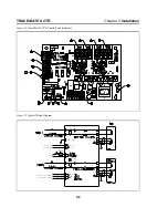
Refer to Figure 2.2 Typical Wiring Diagram, for
power, heater and RTD field connections.


