TRACE
MATE II-CTR
Chapter 3 APPLICATIONS
3.1
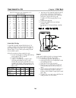
Mechanical Thermostat Replacement
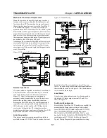
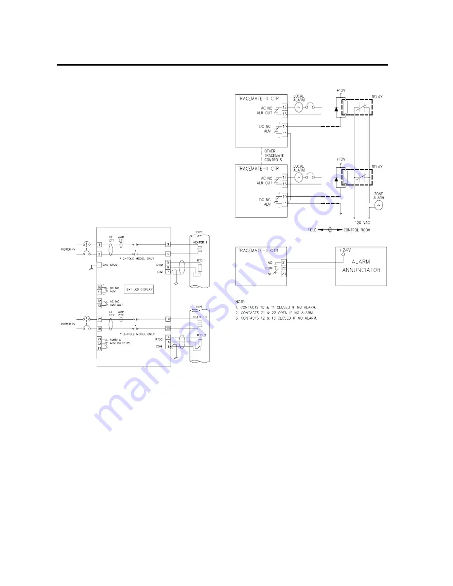
Mount the control unit near the pipe being traced in a
location with easy access. Replace the thermostat capil-
lary tube with an RTD mounted on the pipe and connect
the existing heater and power wires to the TraceMate II-
CTR as shown in Figure 3.1. A 16x1 LCD display is
mounted on the door of TraceMate II-CTR. Instant system
measurements such as pipe temperatures, heater currents,
ground fault currents, and heater on/off status can be seen
on the display. Also, the alarm status of each heater and
their causes are shown on the display. If control power is
not available, the LCD display will go off.
Advantage of this scheme over mechanical thermostats is:
easy setpoint adjustment, ground fault current protection,
early warning of system faults with TraceCheck system
exercising every 24 hours and rapid fault diagnosis in the
event of a problem.
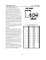
Remote Zone Alarm
If a remote alarm is required, a number of TraceMate II-
CTR control alarms can be connected to give a remote
zone alarm indication in a control room as shown in
Figure 3.2. Once the alarm goes on, maintenance
personnel can be dispatched to the area. The heat trace
point with a problem can be identified by the alarm
messages on the LCD display. For a fast diagnosis and
repair, the alarm message on the display and the status
LED indicators in the TraceMate II-CTR identify the
exact nature of the problem. This simple connection
minimizes control room panel space, allowing a few LCD
displays and indicators to cover a complete plant.
Alarm Annunciator
If an alarm annunciator or programmable controller is
available, terminal 21, 22 & 23 can be used as a low cost
digital interface. These terminals are form C dry con-
tacts. A separate voltage source must be connected across
these terminals as shown in Figure 3.2 for the annuncia-
tor to sense the alarm logic.
Local Alarm
A local visual alarm indicator can also be connected to
the isolated AC alarm output terminals 12 and 13 as
shown in Figure 3.2.
Switching Requirements
Four different TraceMate II-CTR models are available to
accommodate different power rating of electric heat
trace. TM-2SIH1-RTD is rated single-pole 120VAC@
30A; TM-2SIH1-RTD-240V is rated single-pole
240VAC@30A; TM-2DIH2-RTD-208~240V is rated
dual-pole 208~240VAC@30A; TM-2SIH1-RTD-277V is
rated single-pole [email protected] to Figure2.2
Typical Wiring Diagram for power and heater wiring.
Figure 3.1 Thermostat Replacement
Figure 3.2 Alarm Wiring


