2.4
TRACE
MATE II-CTR
Chapter 2 Installation
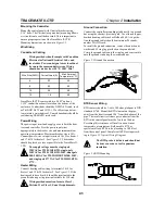
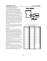
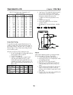
You must install the RTD sensor on the pipe surface or
thermal well before the pipe insulation to ensure proper
thermal contact. The RTD position should be 180° from
the electric heat trace cable which is the coldest spot of
the pipe. The RTD sensor may be secured to the pipe by
fiber-glass tape. If additional wiring is required for the
RTD, shielded 3-lead wire sized 18 or 20AWG must be
used for the RTD sensor to minimize the effects of noise
pickup. A typical RTD installation is shown in Figure 2.4.
Alarm Wiring
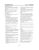
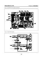
TraceMate II-CTR has two passive alarm contacts. Both
of them are configured as normally closed contacts. Also,
TraceMate II-CTR has a Form C alarm dry contact. Refer
to Figure 2.2 for alarm output terminals.
The AC triac alarm output is rated 12-277Vac, 0.5A. The
DC alarm output is an opto-isolated transition output
rated 30Vdc/100mA, 500mW max. The Form C dry
alarm contact is rated 0.5A 277Vac/0.1A 30Vdc max.
These alarm outputs are designed to interface to
annunciator, panels, PLC or DCS.
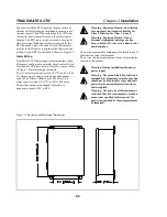
Figure 2.5 Enclosure and Mounting Dimensions
Warning - Explosion Hazard - Substitution
of components may impair suitability for
Class 1, Division 2 or Class 1, Zone 2.
Warning - Explosion Hazard - Do not
disconnect equipment unless power has
been switched off or the area is known to be
non-hazardous.
There are no consumable components contained in any of
the models covered in this manual.
There is no cleaning requirements for any of the modules
covered in this manual.
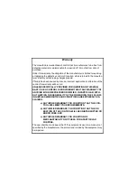
Warning - During installation, disconnect
power supply.
Warning - The ground fault trip function is
intended for equipment protection only and
should not be used in place of ground fault
protection for personnel protection where
this is required.
Warning - The operator of this instrument
is advised that if the instrument is used in a
manner not specified in this manual, the
protection provided by the equipement may
be impaired.


