NETGEAR GS700TS Series User Manual Download Page 34

GS700TS Series Smart Switch Software User Manual

Configuring The Device Using Your Browser

5-5

v1.0, November 2006

Information Buttons

 – The NETGEAR GS700TS Switch web browser contains the 

following information buttons:
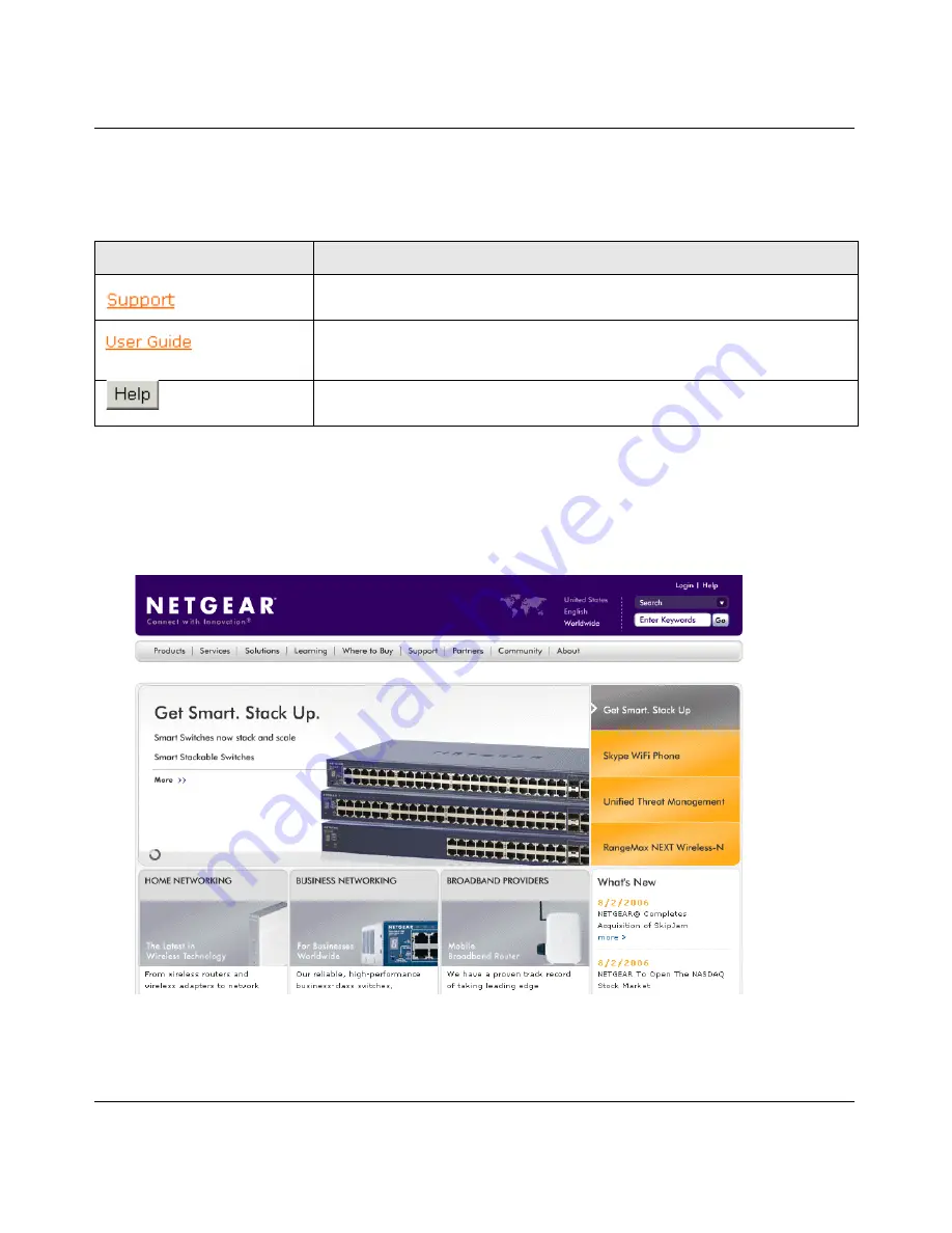
Support Button


The Support section contains information for accessing NETGEAR technical support. 

To access the technical support page:

1.

Click 

Support

 on the NETGEAR home page. The Support section


opens: 

2.

Enter the product name in the Search field. The search results are returned. 

Table 5-1.  Information Buttons

Button

Description

Opens the NETGEAR support page. The NETGEAR technical support 
page URL is http://kbserver.netgear.com/main.asp.

Opens the online manual.

Opens the context sensitive online help.

Figure 5-16

Summary of Contents for GS700TS Series

Page 1: ...202 10228 01 November 2006 v1 0 NETGEAR Inc 4500 Great America Parkway Santa Clara CA 95054 USA GS700TS Series Smart Switch Software User Manual...

Page 2: ...refer to the notes in the operating instructions The Federal Office for Telecommunications Approvals has been notified of the placing of this equipment on the market and has been granted the right to...

Page 3: ...Model Number GS700TS Publication Date November 2006 Product Family Smart Switch Product Name GS700TS Smart Switch with Gigaport Ports Home or Business Product Business Language English Publication Pa...

Page 4: ...v1 0 November 2006 iv...

Page 5: ...Main Screen Switch Setting Configuration Setting 3 4 Main Screen Device Setting Configuration Setting Set 3 5 Main Screen Device Setting Configuration Setting Cancel 3 5 Main Screen Switch Setting Pa...

Page 6: ...rt based Security 5 33 Configuring Passwords 5 37 Defining RADIUS Settings 5 38 Defining TACACS Authentication 5 40 Viewing System Logs 5 42 Logs Configuration 5 43 Viewing the Memory Logs 5 44 Viewin...

Page 7: ...em Files 5 125 Monitoring the Device 5 129 Managing RMON Statistics 5 134 Configuring RMON History 5 137 Defining RMON Events 5 142 Defining RMON Alarms 5 146 Resetting the Factory Default Values 5 15...

Page 8: ...viii v1 0 November 2006...

Page 9: ...tions This manual uses the following typographical conventions Formats This manual uses the following formats to highlight special messages Italics Emphasis books CDs URL names Bold User input Fixed S...

Page 10: ...versions of the full manual and individual chapters How to Print this Manual To print this manual you can choose one of the following several options according to your needs Printing a Page in the HT...

Page 11: ...se the Complete PDF Manual link at the top left of any page Click the Complete PDF Manual link at the top left of any page in the manual The PDF version of the complete manual opens in a browser windo...

Page 12: ...manage the switch using any of the following methods Smartwizard Discovery program Web browser interface After you power up the switch for the first time you can configure it using a utility program c...

Page 13: ...Software User Manual 1 2 Switch Management Overview v1 0 November 2006 For a more detailed discussion of the Smartwizard Discovery Program see Chapter 3 For a more detailed discussion of the Web Brow...

Page 14: ...DHCP server most common as well as if you do not have a DHCP server Network with DHCP Server 1 Connect the GS700TS switch to a DHCP network 2 Power on the GS700TS switch by plugging in power cord 3 I...

Page 15: ...GS700TS Series Smart Switch Software User Manual 2 2 Getting Started v1 0 November 2006 5 Select the switch from the Device List Then click Web Access see Figure 2 2 Figure 2 1...

Page 16: ...h Software User Manual Getting Started 2 3 v1 0 November 2006 6 Start managing your switch via your web browser The default password is password For a detailed description on web management please ref...

Page 17: ...The default IP is 192 168 0 239 3 Install the Smartwizard Discovery program on your computer Start Smartwizard Discovery Chapter 3 has detailed instructions on the Smartwizard Discovery 4 Click Discov...

Page 18: ...GS700TS Series Smart Switch Software User Manual Getting Started 2 5 v1 0 November 2006 Figure 2 4 Figure 2 5...

Page 19: ...v1 0 November 2006 8 Select your switch by clicking on it Then click on Web Access see Figure 2 6 9 Start managing your switch via your web browser The default password is password For a detailed desc...

Page 20: ...rd Discovery is as follows 1 Insert the disc into your CD ROM drive 2 Select the Software folder or click install from Browser auto executed after inserting the Resource CD 3 Run the Setup program to...

Page 21: ...Program v1 0 November 2006 Main Screen Device List Discover The Smartwizard Discovery can discover all switches currently connected on the network Click Discover to view the following switch informati...

Page 22: ...GS700TS Series Smart Switch Software User Manual Smartwizard Discovery Program 3 3 v1 0 November 2006 Product Name System Name Location DHCP Subnet Mask Gateway Firmware Version Figure 3 8...

Page 23: ...ng screen pops up and displays the Product Name and MAC Address From this screen you can modify the following IP Address Displays the currently configured IP address Subnet Mask Displays the currently...

Page 24: ...ord Change 1 Click Password Change from the Switch Setting section The following screen pops up as shown in Figure 3 10 New Password Type any desired password Passwords are case sensitive and can have...

Page 25: ...GS700TS Series Smart Switch Software User Manual 3 6 Smartwizard Discovery Program v1 0 November 2006 For more on Web management see Configuring The Device Using Your Browser...

Page 26: ...ion The following screen opens Firmware Path The location of the new firmware If you do not know the location you can click Browse to locate file Password The default password is password Upgrade Stat...

Page 27: ...additional features as they become available The application software needs to be downloaded from a TFTP server containing the software updates The upgrade procedure and the required equipment are de...

Page 28: ...Procedure 4 2 v1 0 November 2006 4 Enter the location of the new firmware in the Firmware path below Firmware setting Alternatively you can click Browse to locate the file Enter following path tftp t...

Page 29: ...d the new firmware file in non volatile memory The system software is automatically loaded to all stacking members Once the system finishes the firmware upgrade process the switch automatically reboot...

Page 30: ...rowser and includes the following topics Introduction Rebooting the System Defining Device Information Managing Stacking Defining RADIUS Settings Configuring Interfaces Defining IP Interface Defining...

Page 31: ...S700TS switch s home page It includes the following sections Opening the NETGEAR GS700TS Home Page Understanding the Home Page Using The NETGEAR Web Management System Buttons Opening the NETGEAR GS700...

Page 32: ...mart Switch Software User Manual Configuring The Device Using Your Browser 5 3 v1 0 November 2006 3 Press Enter The Logon Page appears 4 Enter a password 5 Click The NETGEAR GS700TS home page is displ...

Page 33: ...VLANs class of service link aggregation aggregating ports multicast support and statistics The Navigation Pane branches can be expanded to view all the components under a specific feature or retracted...

Page 34: ...ormation for accessing NETGEAR technical support To access the technical support page 1 Click Support on the NETGEAR home page The Support section opens 2 Enter the product name in the Search field Th...

Page 35: ...browser GUI management buttons allow network managers to easily configure the device from remote locations The NETGEAR GS700TS Switch web browser GUI contains the following management buttons Rebooti...

Page 36: ...on the left The Reboot Page opens The Reboot Page contains the following field Reboot Unit No Choose the port to be reset or select the option Stack to reboot all stacking members 2 Click The device...

Page 37: ...rt and LED statuses Clicking on a port will bring up the Modify Port Configuration Screen To view the System Zoom Page 1 Click Zoom The System Zoom Page opens Viewing the Device Information The Switch...

Page 38: ...er defined device name The field may contain 0 160 characters System Location Defines the location where the system is currently running The field may contain 0 160 characters System Contact Defines t...

Page 39: ...e is currently in stand alone or stacking mode By default the device runs in stacking mode Jumbo Frame Support Enables Jumbo Frames on the device Jumbo Frames enable the transportation of identical da...

Page 40: ...es are None Indicates that a clock source is not used The clock is set locally SNTP Indicates that the system time is set via an SNTP server Date The system date The field format is Day Month Year For...

Page 41: ...setup one device is selected as the Stacking Master All other devices are named as stack members and assigned a unique Unit ID The Stack Master provides a single point of control and management and a...

Page 42: ...et continues through the stack until it reaches the destination port The system automatically discovers the optimal path by which to send traffic A chain topology connects stacking members from one to...

Page 43: ...cision process If only one Stacking Master enabled unit is present this is the stacking Master If two Stacking Master enabled stacking members are present and one has been manually configured as the S...

Page 44: ...or correct the topology failure and reconnect the unit to the stack Configuration files are changed only through explicit user configuration Configuration files are not automatically modified when Un...

Page 45: ...the stacking members fails A soft switchover is performed via the web interface Switching between the Stacking Master and the Secondary Master results in a limited service loss Any dynamic tables are...

Page 46: ...ack is powered up and completes the boot up process the Master unit is elected within 0 5 seconds The possible field values are Automatically The master is selected automatically by software Force Mas...

Page 47: ...on file is synchronized between Stacking Master and the Secondary Master and continues running on the Secondary Master To switch between stack masters 1 Open the Stack Management Page 2 Select the For...

Page 48: ...This section includes the following sections Defining Port Authentication Viewing EAP Statistics Extensible Authentication Protocol To define the port authentication properties 1 Click Security Port A...

Page 49: ...that no authentication method is used to authenticate the port Guest VLAN Specifies whether the Guest VLAN is enabled on the device The possible field values are Enable Enables using a Guest VLAN for...

Page 50: ...on Page contains the following fields Unit No Indicates the stacking number ID Displays a list of interfaces on which port based authentication is enabled User Name Displays the supplicant user name C...

Page 51: ...ending EAP Defines the amount of time in seconds that lapses before EAP requests are resent The field default is 30 seconds Max EAP Requests Displays the total amount of EAP requests sent If a respons...

Page 52: ...0 November 2006 2 Click an ID The Modify Port Security Page opens 3 Modify the relevant fields 4 Click The port authentication settings are defined and the device is updated Viewing EAP Statistics The...

Page 53: ...h Rate Indicates the amount of time that passes before the EAP statistics are refreshed The possible field values are No Refresh Indicates that the EAP statistics are not refreshed 15 Seconds Indicate...

Page 54: ...attached to the most recently received EAPOL frame Last Frame Source Indicates the source MAC address attached to the most recently received EAPOL frame Enabling Storm Control Storm Control limits th...

Page 55: ...displayed Interface Displays the port number for which the Storm Control information is displayed Broadcast Control Indicates if forwarding broadcast packet types is enabled on the interface for whic...

Page 56: ...eshold Indicates the maximum rate kilobits per second at which unknown packets are forwarded The range is 3500 250 000 kbps The default value is 200 kbps 2 Click an interface The Storm Control Modify...

Page 57: ...e ACL are either admitted or denied entry and the ingress port is disabled If they are denied entry the user can disable the port To implement ACLs first define the ACL to specify what actions should...

Page 58: ...MAC based ACLs Remove ACL Removes the ACLs The possible field values are Checked Removes the selected MAC based ACL Unchecked Maintains the MAC based ACLs ID Matches the packet s VLAN ID to the ACE T...

Page 59: ...dicates the destination MAC Address wild card mask Wildcards are used to mask all or part of a destination IP Address Wild card masks specify which bits are used and which bits are ignored A wild card...

Page 60: ...MAC Based Rule page contains the following fields ACL Name Displays the user defined MAC based ACLs New Rule Priority Indicates the rule priority which determines which rule is matched to a packet on...

Page 61: ...Ports are reactivated from the Port Management screen Defining Access Control Lists Binding To define ACL Binding 1 Click Security Access Control ACL Binding The ACL Binding Page opens The ACL Binding...

Page 62: ...ports are displayed 3 Select the ACL Name and ports to be bound 4 Click Apply The ACL Binding is defined and the device is updated Port based Security Network security can be increased by limiting ac...

Page 63: ...nism is invoked It provides the following options for unauthorized packets arriving at a locked port Forwarded Discarded with no trap Discarded with a trap Shuts down the port Locked port security als...

Page 64: ...d packets are forwarded only from MAC addressees that have been learned prior to locking the port Max Entries Specifies the number of MAC address that can be learned on the port The Max Entries field...

Page 65: ...ce Displays the port or LAG name The possible field values are All Ports of the Stack Indicates the ports of the stack from which Storm Control is enabled All LAGs Indicates the LAGs of the stack from...

Page 66: ...3 Modify the relevant fields 4 Click The port security settings are defined and the device is updated Configuring Passwords The Password Settings Page contains parameters for configuring device passw...

Page 67: ...DIUS server TACACS Authentication occurs at the TACACS server None No authentication type is applied Old Password Indicates the current password used to access the system New Password Defines a new pa...

Page 68: ...efines the RADIUS Server IP address Authentication Port Identifies the authentication port The authentication port is used to verify the RADIUS server authentication The authenticated port default is...

Page 69: ...ication 2 Define the relevant fields 3 Click The RADIUS Servers are enabled and the system is updated Defining TACACS Authentication Terminal Access Controller Access Control System TACACS provides ce...

Page 70: ...tion fields Host IP Address Defines the TACACS Server IP address Key String Defines the default authentication and encryption key for TACACS communication between the device and the TACACS server Auth...

Page 71: ...g Severity Levels This section provides information for managing logs The logs enable viewing device events in real time and recording the events for later usage Logs record and manage events and repo...

Page 72: ...everity level When a severity level is selected all severity level choices above the selection are selected automatically To enable event logging 1 Click Logs Logs Configuration The Logs Configuration...

Page 73: ...ts remain functional Error A device error has occurred for example if a single port is offline Warning The lowest level of a device warning The device is functioning but an operational problem has occ...

Page 74: ...ck Logs Memory Logs The Memory Logs Page opens The Memory Logs Page contains the following fields ID Displays the table entry number Log Index Displays the log number Log Time Displays the time at whi...

Page 75: ...ty and a description of the log message The message log is available after reboot To view the message logs 3 Click Logs Flash Logs The Flash Logs Page opens The Flash Logs Page contains the following...

Page 76: ...e log servers New log servers can be defined and the log severity sent to each server To open the Server Logs Page 1 Click Logs Server Logs The Server Logs Page opens The Server Logs Page contains the...

Page 77: ...s are Local 0 Local 7 Description A user defined server description Minimum Severity Indicates the minimum severity from which logs are sent to the server For example if Notice is selected all logs wi...

Page 78: ...This section contains information for configuring ports and contains the following topic Defining Port Parameters Defining LAG Members Defining Port Parameters The Port Configuration Page contains fi...

Page 79: ...negotiation is disabled and the port speed is set to 10M or 100M This field cannot be configured on LAGs The possible field values are Full The interface supports transmission between the device and i...

Page 80: ...two end stations are connected to each other a crossover cable is used to ensure that the correct pairs are connected The possible field values are Auto Uplink Use to automatically detect the cable t...

Page 81: ...urrently receiving and transmitting traffic Disable The port is currently disabled and is not currently receiving or transmitting traffic Admin Speed Displays the configured rate for the port The port...

Page 82: ...Mbps speed port and full duplex mode setting 100 Half Indicates that the port advertises for a 100 Mbps speed port and half duplex mode setting 100 Full Indicates that the port advertises for a 100 M...

Page 83: ...me media type A VLAN is not configured on the port The port is not assigned to a different LAG Auto negotiation mode is not configured on the port The port is in full duplex mode All ports in the LAG...

Page 84: ...ational status The possible field values are Up Indicates the LAG is currently linked and forwarding traffic Down Indicates the LAG is currently not linked LAG Speed Displays the configured rate for t...

Page 85: ...a time Auto Negotiation Displays the auto negotiation status on the LAG Auto negotiation is a protocol between two link partners that enables a port to advertise its transmission rate duplex mode and...

Page 86: ...LAG Link Aggregation Control Protocol automatically bundles ports together in a LAG Admin Status Indicates whether the port is currently operational or non operational The possible field values are Up...

Page 87: ...rent LAG Speed Indicates the current configured rate for the LAG Admin Duplex Displays the port duplex mode This field is configurable only when auto negotiation is disabled and the port speed is set...

Page 88: ...rocess The possible field values are those specified in the Admin Advertisement field Neighbor Advertisement Indicates the neighboring port s advertisement settings The field values are identical to t...

Page 89: ...fields LAG Displays the LAG number Name Displays LAG the name Link State Displays the LAG operational status The possible field values are Link Present Indicates the LAG is currently linked and forwar...

Page 90: ...and the device is updated Configuring LACP LAG ports can contain different media types if the ports are operating at the same speed Aggregated links can be set up manually or automatically establishe...

Page 91: ...hest priority is 1 and the lowest is 65535 The field default is 1 Unit No Displays the stacking member for which the LAG parameters are defined Interface Displays the interface number to which timeout...

Page 92: ...N which combine user stations and network devices into a single unit regardless of the physical LAN segment to which they are attached VLANs allow network traffic to flow more efficiently within subgr...

Page 93: ...fic is generated VLAN tagging provides a method of transferring VLAN information between VLAN groups VLAN tagging attaches a 4 byte tag to packet headers The VLAN tag indicates to which VLAN the packe...

Page 94: ...ies Page contains the following fields ID Displays the VLAN ID Name Displays the user defined VLAN name Type Displays the VLAN type The possible field values are Static Indicates the VLAN is user defi...

Page 95: ...witch Software User Manual 5 66 Configuring The Device Using Your Browser v1 0 November 2006 2 Click The Add VLAN Page opens 3 Define the relevant fields 4 Click The VLAN ID is defined and the device...

Page 96: ...erties Page opens 2 Click on an Interface to access the Figure 5 52 The Figure 5 52 opens 3 Modify the relevant fields 4 Click The VLAN Settings are modified and the device is updated Defining VLAN Me...

Page 97: ...ame of the VLAN VLAN Type Indicates the VLAN type The possible field values are Static Indicates the VLAN is user defined Default Indicates the VLAN is the default VLAN The default VLAN is enabled 2 D...

Page 98: ...l ports are tagged Click All ports are untagged Click All changes are cancelled and return to the previous settings 3 Click The VLAN Membership is defined and the device is updated Defining VLAN PVID...

Page 99: ...g fields Unit No Displays the stacking member for which the PVID information is displayed Interface Displays the interface to which the PVID tag is assigned The possible field values are Port Displays...

Page 100: ...e statically defined or may be retrieved using the Dynamic Host Configuration Protocol DHCP The IP Interface Page also contains information for defining the default gateway When using DHCP network dev...

Page 101: ...using DHCP Static IP Address The IP Address is set manually IP Address Displays the currently configured IP address Subnet Mask Displays the currently configured IP address mask Gateway Defines the d...

Page 102: ...Static addresses are configured manually An address becomes associated with a port by learning the port from the frame s source address but if a frame that is addressed to a destination MAC address i...

Page 103: ...owing fields ID Indicates the stacking number VLAN ID Displays the VLAN ID number to which the entry refers MAC Address Displays the MAC address to which the entry refers Interface Displays the interf...

Page 104: ...ase Back Displays the previous page of VLANs in the Statistics Address table if there is a previous page Next Displays the following page of VLANs in the Statistics Address table if there is a page fo...

Page 105: ...ance Development 3 Define the relevant fields 4 Click The forwarding database information is modified and the device is updated To modify a static address entry 1 Click Address Table Static Addresses...

Page 106: ...ameters for querying information in the Dynamic MAC Address Table including the interface type MAC addresses VLAN and table storing The Dynamic MAC Address table contains information about the aging t...

Page 107: ...amic MAC Address table before it is timed out if no traffic from the source is detected The default value is 300 seconds Clear Table Removes the current values from the table Interface Specifies the i...

Page 108: ...le is currently queried Back Displays the previous page of the configuration information if there is a previous page Next Displays the following page of the configuration information if there is a pag...

Page 109: ...lds Spanning Tree State Indicates whether STP is enabled on the device The possible field values are Enable Enables STP on the device Disable Disables STP on the device Priority Specifies the bridge p...

Page 110: ...e The default is zero Root Path Cost The cost of the path from this bridge to the Root Bridge Topology Changes Counts Specifies the total amount of STP state changes that have occurred Last Topology C...

Page 111: ...od used to assign default path cost to STP ports The possible field values are Short Specifies 1 through 65 535 range for port path cost This is the default value Long Specifies 1 through 200 000 000...

Page 112: ...face The interface for which the information is displayed The possible field values are All Ports of the Stack Selects all ports on the stack All LAGs Selects all LAGs on the stack All Ports of Unit N...

Page 113: ...ing Indicates that the port is currently blocked and cannot forward traffic or learn MAC addresses Blocking is displayed when STP is enabled Speed Indicates the speed at which the port is operating Pa...

Page 114: ...over less time sensitive applications For example under SP voice over IP VoIP traffic can be prioritized so that it is forwarded before FTP or email SMTP traffic Weighted Round Robin Ensures that a si...

Page 115: ...n the device Trust Mode Defines which packet fields to use for classifying packets entering the device When no rules are defined the traffic containing the predefined packet CoS field is mapped accord...

Page 116: ...meters are defined Default CoS Determines the default CoS value for incoming packets for which a VLAN tag is not defined Restore Defaults Restores the factory CoS default settings to the selected port...

Page 117: ...field Set Default User Priority Sets the default user priority The possible field values are 0 7 The default CoS value is 0 With the default settings 0 is the lowest and 7 is the highest priority 3 M...

Page 118: ...tains the following fields Strict Priority Specifies whether traffic scheduling is based strictly on the queue priority WRR Assigns WRR weights to queues to prevent a specific application from consumi...

Page 119: ...Committed Information Rate Indicates the rate that data is transmitted The rate is averaged over a minimum time increment The Bandwidth Page allows network managers to define the bandwidth settings fo...

Page 120: ...rate limiting to kilobits per second The field range is 3500 1 000 000 Kbps Egress Shaping Rate on Selected Port Determines the egress port bandwidth settings for the selected interface The possible f...

Page 121: ...es the port number LAG No Indicates the LAG number Egress Shaping Rate on Selected Port Indicates if rate limiting is enabled on the interface The possible field values are Enable Enables engress rate...

Page 122: ...g on the interface Rate Limit Defines the amount of bandwidth assigned to the interface 3 Define the relevant fields 4 Click The bandwidth settings are saved to interface and the device is updated Map...

Page 123: ...which the CoS priority is mapped Four traffic priority queues are supported The lowest priority is 1 and is the highest is 4 Restore Defaults Restores the device factory defaults for mapping CoS valu...

Page 124: ...DSCP In Displays the incoming packet s DSCP value Queue Specifies the traffic forwarding queue to which the DSCP priority is mapped Four traffic priority queues are supported 2 Define the relevant fie...

Page 125: ...st the disclosure of message content Cipher Block Chaining CBC is used for encryption Either authentication is enabled on an SNMP message or both authentication and privacy are enabled on an SNMP mess...

Page 126: ...ins the following fields Local Engine ID 10 64 Hex Characters Displays the local device Engine ID The field value is a hexadecimal string Each byte in hexadecimal character strings is two hexadecimal...

Page 127: ...sers Page provides information for creating SNMP groups and assigning SNMP access control privileges to SNMP groups Groups allow network managers to assign access rights to specific device features or...

Page 128: ...ted to a remote SNMP entity If the Engine ID is defined remote devices receive inform messages Authentication Displays the method used to authenticate users The possible field values are MD5 Key Users...

Page 129: ...n and privacy keys are entered to define the authentication key If only authentication is required 16 bytes are defined If both privacy and authentication are required 32 bytes are defined Each byte i...

Page 130: ...vanced SNMP Users The SNMP Users Page opens 2 Select a SNMP group The Modify Users Page opens 3 Modify the relevant fields 4 Click The SNMP user is defined and the device is updated Defining SNMP Grou...

Page 131: ...p Name Displays the user defined group to which access control rules are applied The field range is up to 30 characters Security Model Defines the SNMP version attached to the group The possible field...

Page 132: ...s that the SNMP message s origin is authenticated Privacy Encrypts SNMP messages Operation Defines the group access rights The possible field values are Read Management access is restricted to read on...

Page 133: ...want to modify The Modify Groups Page opens 3 Modify the relevant fields 4 Click The SNMP group profile is modified and the device is updated Defining SNMP Views SNMP Insert space views provide or blo...

Page 134: ...he view name can contain a maximum of 30 alphanumeric characters ID Indicates the stacking number Object ID Subtree Displays the device feature OID included in or excluded from the selected SNMP view...

Page 135: ...munities in the SNMP Communities Page When the community names are changed access rights are also changed SNMP communities are defined only for SNMP v1 and SNMP v2c The Communities Page is divided int...

Page 136: ...ll as permissions to modify the community View Name Contains a list of user defined SNMP views Delete Removes a community The possible field values are Checked Removes the selected SNMP community Unch...

Page 137: ...Series Smart Switch Software User Manual 5 108 Configuring The Device Using Your Browser v1 0 November 2006 To define SNMP communities 1 Click Advanced SNMP Communities The Communities Page opens Figu...

Page 138: ...oftware User Manual Configuring The Device Using Your Browser 5 109 v1 0 November 2006 2 Click The Add Communities Page opens 3 Define the relevant fields 4 Click The SNMP community is added and the d...

Page 139: ...y Communities Page opens 3 Modify the relevant fields 4 Click The SNMP community is modified and the device is updated Trap Station Management The Trap Station Management Page contains information for...

Page 140: ...on Management Page opens The Trap Station Management Page is divided into the following tables SNMPv1 2c Notification Recipient SNMPv3 Notification Recipient SNMPv1 2c Notification Recipient The SNMP...

Page 141: ...amount of times the device re sends an inform request The default is 3 seconds Delete Removes the currently selected recipient The possible field values are Checked Removes the selected recipient fro...

Page 142: ...nding informs The field range is 1 300 The default is 10 seconds Retries The amount of times the device resends an inform request The field range is 1 255 The default is 3 Delete Removes the currently...

Page 143: ...ed SNMP Trap Station Management The Trap Station Management Page opens 2 Click an ID The Modify Trap Station Management Page opens 3 Modify the relevant fields 4 Click The SNMP Notification recipients...

Page 144: ...vice can send SNMP notifications The possible field values are Enable Enables SNMP notifications Disable Disables SNMP notifications Authentication Notifications Specifies whether SNMP authentication...

Page 145: ...Settings The Trap Filter Settings Page opens The Trap Filter Settings Page contains the following fields Filter Name Contains a list of user defined notification filters ID Indicates the Trap Filter...

Page 146: ...e Add Trap Filter Settings Page opens 3 Define the relevant fields 4 Click The SNMP Trap filter is defined and the device is updated Configuring Multicast Forwarding Multicast forwarding allows a sing...

Page 147: ...forwarding is functional However irrelevant ports also receive the multicast causing increased network traffic Multicast forwarding filters enable forwarding of Layer 2 packets to port subsets defined...

Page 148: ...Status Indicates if IGMP Snooping is enabled on the device IGMP Snooping can be enabled only if Bridge Multicast Filtering is enabled The possible field values are Checked Enables IGMP Snooping on the...

Page 149: ...a message before timing out The default time is 260 seconds MRouter Timeout Indicates the amount of the time the multicast router waits to receive a message before it times out The default value is 3...

Page 150: ...defined and the device is updated Defining Multicast Groups The Multicast Group Page displays the ports and LAGs attached to the multicast service group in the Ports and LAGs tables The Port and LAG t...

Page 151: ...ng is enabled on the device The possible field values are Checked Enables multicast filtering on the device Unchecked Disables multicast filtering on the device If multicast filtering is disabled mult...

Page 152: ...e Ports that can be added to a multicast service Interface Status Indicates the interface status The possible field values are Static The interface is statistically configured to the multicast group F...

Page 153: ...nabled multicast packets are forwarded to the appropriate port or VLAN Unless LAGs are defined only a Multicast Forward All table displays To define Multicast forward all settings 1 Click Advanced Mul...

Page 154: ...es the port to the multicast router or switch as a static port Forbidden Forbidden The port cannot be attached Excluded Excluded The port is not attached 2 Define the relevant fields 3 Click The Multi...

Page 155: ...mart Switch Software User Manual 5 126 Configuring The Device Using Your Browser v1 0 November 2006 To back up files 1 Click File Management File Upload from Switch The File Upload from Switch Page op...

Page 156: ...Server IP Address to which the firmware upload file is uploaded Destination File Name Specifies the source file name to be uploaded Configuration Upload from Switch The Configuration Upload from Swit...

Page 157: ...g fields Firmware Download to Switch Configuration Download to Switch Firmware Download to Switch The Firmware section contains the following fields TFTP Server IP Address Specifies the TFTP Server IP...

Page 158: ...ollowing topics Configuring Port Mirroring Performing Copper Cable Tests Configuring Port Mirroring Port mirroring monitors and mirrors network traffic by forwarding copies of incoming and outgoing pa...

Page 159: ...tination Port Defines the port number to which port traffic is copied Source Port Indicates the port from which the packets are mirrored Type Indicates the port mode configuration for port mirroring T...

Page 160: ...ndicates the port is not currently monitored Delete Removes the port mirroring session The possible field values are Checked Removes the selected port mirroring sessions Unchecked Maintains the port m...

Page 161: ...per Cable Tests The Performing Copper Cable Tests contains fields for performing tests on copper cables Cable testing provides information about where errors occurred in the cable the last time a cabl...

Page 162: ...pper cable test results are displayed Interface Specifies the port to which the cable is connected Test Result Displays the cable test results Possible values are No Cable Indicates that a cable is no...

Page 163: ...be performed when the port is up and operating at 1 Gbps Managing RMON Statistics This section contains information for viewing the Remote Monitoring Statistics RMON Statistics allow network managers...

Page 164: ...Port Defines the specific port for which RMON statistics are displayed LAG Defines the specific LAG for which RMON statistics are displayed Refresh Rate Defines the amount of time that passes before t...

Page 165: ...occurred on the interface since the device was last refreshed Undersize Packets Displays the number of undersized packets less than 64 octets received on the interface since the device was last refres...

Page 166: ...tistics 2 Click The RMON statistics counters are cleared Configuring RMON History This section contains the following topics Defining RMON History Control Viewing the RMON History Table Defining RMON...

Page 167: ...splays the interface from which the history samples were taken The possible field values are Port Specifies the port from which the RMON information was taken LAG Specifies the LAG from which the RMON...

Page 168: ...rmation The field range is 0 20 characters Delete Removes History Control entries The possible field values are Checked Removes the selected History Control entry Unchecked Maintains the current Histo...

Page 169: ...Control The History Control Page opens 2 Click a history entry number The Modify History Control Page opens 3 Modify the relevant fields 4 Click The entry is modified and the device is updated Viewin...

Page 170: ...ON information The field range is 0 20 characters Sample No Indicates the sample number from which the statistics were taken Drop Events Displays the number of dropped events that have occurred on the...

Page 171: ...d on the interface since the device was last refreshed Fragments Displays the number of fragments packets with less than 64 octets excluding framing bits but including FCS octets received on the inter...

Page 172: ...nts 1 Click Statistics RMON RMON Events Events Control The Events Control Page opens The Events Control Page contains the following fields ID Indicates the stacking number Event Entry Displays the eve...

Page 173: ...Indicates that the event is both a log entry and a trap None Indicates that no event occurred Time Displays the time that the event occurred Owner Displays the device or user that defined the event De...

Page 174: ...N event 1 Click Statistics RMON RMON Events Events Control The Events Control Page opens 2 Click The Add Events Control Page is opens 3 Define the relevant fields 4 Click The port mirroring session is...

Page 175: ...the following fields ID Indicates the Events Logs Page table entry Event Displays the RMON Events Log No Displays the log number Log Time Displays the time when the log entry was entered Description...

Page 176: ...y Indicates a specific alarm Counter Name Displays the selected MIB variable Interface Displays interface for which RMON statistics are displayed The possible field values are Port Displays the RMON s...

Page 177: ...the management system If the device is not reset the entry remains in the Log Table TRAP Indicates that an SNMP trap is generated and sent via the Trap mechanism The Trap can also be saved using the T...

Page 178: ...Software User Manual Configuring The Device Using Your Browser 5 149 v1 0 November 2006 2 Click The Add RMON Alarms Page opens 3 Define the relevant fields 4 Click The RMON alarm is added and the dev...

Page 179: ...Using Your Browser v1 0 November 2006 To modify RMON alarms 1 Click Statistics RMON RMON Alarms The RMON Alarms Page opens 2 Select an ID The Modify RMONS Alarms Page opens 3 Modify the relevant fiel...

Page 180: ...e switch Restoring factory defaults results in erasing the configuration file The stacking defaults are not restored from this page including The stacking mode The stacking cables The Unit ID numberin...

Page 181: ...witch to default settings by using the Factory Reset function from a web browser Table 1 Default Settings Feature GS700TS Default Setting Port Speed Auto negotiation Port Duplex Auto negotiation Flow...

Page 182: ...c Addresses 5 77 E EAP Statistics 5 23 Engine ID 5 97 F Factory Reset 5 151 File Upload 5 125 Firmware Download 5 128 Firmware Upgrade 3 7 Firmware Upload 5 127 Flash Logs 5 46 Forwarding Address Tabl...

Page 183: ...ble 5 140 RMON Statistics 5 134 S Server Logs 5 47 SNMP 5 95 SNMP Communities 5 106 SNMP Groups 5 101 SNMP Users 5 98 SNMP Views 5 104 SNMPv1 2c 5 111 SNMPv3 5 112 Spanning Tree 5 79 5 82 Stack Manage...

Page 184: ...GS700TS Series Smart Switch Software User Manual Index 3 v1 0 November 2006...

Page 185: ...GS700TS Series Smart Switch Software User Manual Index 4 v1 0 November 2006...

Page 186: ...GS700TS Series Smart Switch Software User Manual Index 5 v1 0 November 2006...

Page 187: ...GS700TS Series Smart Switch Software User Manual Index 6 v1 0 November 2006...

Page 188: ...GS700TS Series Smart Switch Software User Manual Index 7 v1 0 November 2006...

Page 189: ...GS700TS Series Smart Switch Software User Manual Index 8 v1 0 November 2006...

Reviews: