Server Safety Information
193
10.7. System Access Warnings
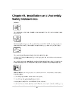
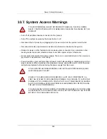
TO AVOID PERSONAL INJURY OR PROPERTY DAMAGE, THE FOLLOWING
SAFETY INSTRUCTIONS APPLY WHENEVER ACCESSING THE INSIDE OF THE
PRODUCT:
• Turn off all peripheral devices connected to this product.
• Turn off the system by pressing the power button to off.
• Disconnect the AC power by unplugging all AC power cords from the system or wall outlet.
• Disconnect all cables and telecommunication lines that are connected to the system.
• Retain all screws or other fasteners when removing access cover(s). Upon completion of ac-
cessing inside the product, refasten access cover with original screws or fasteners.
• Do not access the inside of the power supply. There are no serviceable parts in the power sup-
ply. Return to manufacturer for servicing.
• Power down the server and disconnect all power cords before adding or replacing any non hot-
plug component. When replacing a hot-plug power supply, unplug the power cord to the power
supply being replaced before removing the power supply from the server.
IF THE SERVER HAS BEEN RUNNING, ANY INSTALLED PROCESSOR(S) AND
HEAT SINK(S) MAY BE HOT.
UNLESS YOU ARE ADDING OR REMOVING A HOT-PLUG COMPONENT, AL-
LOW THE SYSTEM TO COOL BEFORE OPENING THE COVERS. TO AVOID THE
POSSIBILITY OF COMING INTO CONTACT WITH HOT COMPONENT(S) DURING
A HOT-PLUG INSTALLATION, BE CAREFUL WHEN REMOVING OR INSTALLING
THE HOT-PLUG COMPONENT(S).
TO AVOID INJURY DO NOT CONTACT MOVING FAN BLADES. IF YOUR SYSTEM
IS SUPPLIED WITH A GUARD OVER THE FAN, DO NOT OPERATE THE SYSTEM
WITHOUT THE FAN GUARD IN PLACE.
Summary of Contents for Demos R420 M2
Page 1: ...Netberg Demos R420 M2 server User manual...
Page 2: ...Netberg Demos R420 M2 server User manual...
Page 12: ...1 Chapter 1 Safety Information...
Page 19: ...8 Chapter 2 About the Server...
Page 32: ...21 Chapter 3 Installing Hardware...
Page 93: ...82 Chapter 4 Connectors...
Page 95: ...Connectors 84 Figure 4 1 Mainboard Overview...
Page 108: ...Connectors 97 4 9 Sensor Board Connectors Figure 4 13 Sensor Board 1 I2C Connector...
Page 109: ...98 Chapter 5 Cable Routing...
Page 110: ...Cable Routing 99 5 1 Cable Routing for 12 x 3 5 Hard Drives Configuration...
Page 111: ...Cable Routing 100 5 2 Cable Routing for 24 x 2 5 Hard Drives Configuration...
Page 112: ...101 Chapter 6 BIOS...
Page 125: ...BIOS 114 6 3 1 5 CPU Advanced PM Tuning...
Page 172: ...BIOS 161 6 4 2 View FRU Information...
Page 176: ...BIOS 165 Menu Fields Settings Comments Network Device BBS Priorities 1...
Page 182: ...171 Chapter 7 Rail Kit Assembly...
Page 186: ...Rail Kit Assembly 175 Figure 7 3 Tightening the Thumbscrews...
Page 187: ...176 Chapter 8 Troubleshooting...

