background image

User’s Manual 


52 


NOTE:  Event related functions are not supported for network devices that use the 

ONVIF

TM

 Conformance 

protocol, 

and some other functions may not be supported depending on the settings of the device. 


Refer to the network device manufacture’s instructions about enabling the ONVIF

TM

 Conformance protocol 

in the device, as procedures may differ for each model.


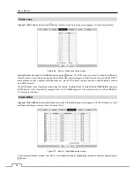
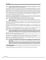
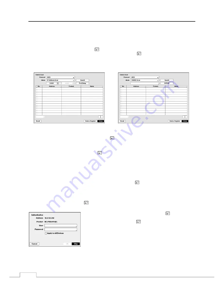
Highlight the box beside 

Mode

, and press the 

 button.  You can select the scan mode from: 

Auto Scan (LAN)

IP 

Address Scan

 and 

DVRNS Scan

.  Select the desired mode and press the   button. 


NOTE:  If the IP address range of the device is different from that of the DVR, the DVR considers the IP address 

invalid.  In this case, you must change the device’s IP address to register the device. 


The 

DVRNS Scan

 mode is not supported when the 

ONVIF

TM

 Conformance 

protocol is selected.


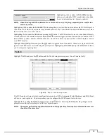
Selecting 

Auto Scan (LAN) 

from Mode scans network devices automatically. 


Selecting 

IP Address Scan 

from Mode scans network devices by entering a specific IP address or adjusting the IP 

address range.  Highlighting 

Port Setup

 and pressing the   button allows you to set the port number used for remote 

monitoring. 


Selecting 

DVRNS Scan 

from Mode scans network devices by entering the IP address or domain name of the network 

device.  Highlighting 

DVRNS

 and pressing the   button allows you to set the port number of the DVRNS server. 


NOTE:  For the DVRNS Scan feature to work, the network device should be registered on the DVRNS server.


You can use the domain name instead of IP address if you set up the DNS Server when setting up the 
Network – IP Address. 


Using the IP Address Scan, you can search for a network device that cannot be searched for using the 
Auto Scan (LAN) mode. 


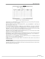
After selecting the desired scan mode, highlighting 

Search

 and pressing the 

 button, the system searches for network 

devices and displays them in the list.  Selecting 

Reset

 allows you to delete the search results list. 


NOTE:  Depending on the model of network device, the device may not be supported even though the DVR supports 

the device's protocol.  Ask your dealer or distributor about supported device models.


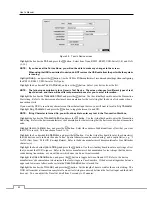
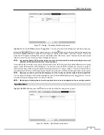
Highlight 

Device Register

 and press the   button to register the selected network device(s) from the list.  An Authentication 

screen appears.  Setting up the Authentication is required to register the network device to the DVR. 


Highlight the box beside 

User

/

Password

 and press the 

 button.  A virtual 

keyboard appears allowing you to enter the user ID and password.  Highlight 

Apply to All Devices

 and press the   button to apply the same authentication 

information to all the network devices in the list.  When selecting multiple 
network devices in the list, selecting 

Skip

 skips the authentication settings 

for the current network device and displays the Authentication screen of the 
next network device.


NOTE:  When registering a four-channel network video transmitter using the iNEX protocol, all four cameras are 

counted regardless of whether or not some or all cameras are disabled.


Summary of Contents for 16-channel models

Page 1: ......

Page 2: ......

Page 3: ...NERATES USES AND CAN RADIATE RADIO FREQUENCY ENERGY AND IF NOT INSTALLED AND USED IN ACCORDANCE WITH THE INSTRUCTION MANUAL MAY CAUSE HARMFUL INTERFERENCE TO RADIO COMMUNICATIONS OPERATION OF THIS EQUIPMENT IN A RESIDENTIAL AREA IS LIKELY TO CAUSE HARMFUL INTERFERENCE IN WHICH CASE USERS WILL BE REQUIRED TO CORRECT THE INTERFERENCE AT THEIR OWN EXPENSE WARNING CHANGES OR MODIFICATIONS NOT EXPRESSL...

Page 4: ...echnician to restore the equipment to its normal operation E If the equipment has been dropped or the cabinet damaged F When the equipment exhibits a distinct change in performance this indicates a need for service 15 Replacement Parts When replacement parts are required be sure the service technician has used replacement parts specified by the manufacturer or that have the same characteristics as...

Page 5: ...ideo Out 6 Power Cord Connector 7 Chapter 3 Configuration 9 Front Panel Controls 9 Camera Buttons 1 to 16 10 Enter Button 10 Arrow Buttons 10 Menu Button 10 ZOOM Button 11 PTZ Button 11 Panic Button 11 LED 11 Display Button 11 Monitor Button 11 Bookmark Button 11 Freeze Button 11 Alarm Button 11 Playback Buttons 12 Jog Dial Shuttle Ring 12 USB Port 12 ID Button on Remote Control 12 Sequence Button...

Page 6: ...n 39 Network 41 Device Setup 41 Local Audio 41 Network Audio 42 Alarm Out 42 Remote Control 43 Display Setup 44 OSD 44 Primary Monitor 45 Secondary Monitor 46 Spot Monitor 47 Status Setup 48 Event 48 Storage 49 Camera Setup 49 General 49 PTZ 50 Network Camera 51 Chapter 4 Operation 55 Turning on the Power 55 Live Monitoring 55 Live Monitoring Menu 56 Active Cameo Mode 58 Zoom Mode 58 PTZ Mode 58 E...

Page 7: ...ard 77 Web Monitoring Mode 78 Web Search Mode 79 Time Overlap 81 Remote Setup of Network Devices 82 Map of Screens 85 Troubleshooting 86 System Log Notices 86 Error Code Notices 87 Connector Pin Outs 87 RS485 Connector Pin Outs 87 I O Connector Pin Outs 88 Specifications 88 List of Illustrations Figure 1 Typical DVR installation 2 Figure 2 16 Channel DVR rear panel 3 Figure 3 16 Channel DVR front ...

Page 8: ...reen 41 Figure 31 Device Local Audio setup screen 42 Figure 32 Device Network Audio setup screen 42 Figure 33 Device Alarm Out setup screen 43 Figure 34 Device Remote Control setup screen 44 Figure 35 Display OSD setup screen 44 Figure 36 Display Primary Monitor setup screen 45 Figure 37 Display Secondary Monitor setup screen 47 Figure 38 Display Spot Monitor setup screen 47 Figure 39 Status Event...

Page 9: ...io Playback Text Input for ATM and POS Alarm Connections Include Input Output and Reset Input Built in Alarm Buzzer Live or Recorded Video Access via Ethernet Time Synchronization using industry standard protocol Built in DVD RW Drive IR Remote Control Self diagnostics with automatic notification including hard disk drive S M A R T protocol Technical Overview In addition to replacing both a time l...

Page 10: ...your DVR remotely by connecting via Ethernet There are eSATA and iSCSI ports that can be used to record or archive eSATA interface only video to external hard disk drives and there are two USB ports that can be used to upgrade the system or copy video clips to external hard disk and flash drives Figure 1 Typical DVR installation NOTE This manual covers the 8 and 16 channel digital video recorders ...

Page 11: ...stall the DVR Refer to the installation manuals for the other items that make up part of your system Figure 2 16 Channel DVR rear panel Video Input Video Loop Through Factory Reset Switch HD SD Out Selector Network Port iSCSI Port eSATA Port RS232C Port RS485 Port Alarm Input Output Audio In Out Video Out Power Cord Connector Your DVR can be used with either NTSC or PAL equipment NOTE You cannot m...

Page 12: ...ut Selector An HD SD Out selector is provided to select the monitor display mode between HD High Definition and SD Standard Definition Setting the selector to the HD OUT position sends HD video to the connected HDMI and VGA monitors and setting to the SD OUT position sends SD video to the connected composite BNC monitor Network Port The DVR can be networked using the 10Mb 1Gb Ethernet connector Co...

Page 13: ... the DVR to react to events Mechanical or electrical switches can be wired to the AI Alarm In and GND Ground connectors The threshold voltage of electrical switches for NC Normally Closed is above 2 4V and for NO Normally Open is below 0 3V and should be stable at least 0 5 seconds to be detected The voltage range of alarm input is from 0V to 5V See Chapter 3 Configuration for configuring alarm in...

Page 14: ...on the primary monitor will be disabled in the HD display mode Monitor Connection Examples HD Display Mode SD Display Mode NOTE Connect the monitor before the DVR boots so that video can be displayed on the monitor with the resolution you have set during system setup If you want to use both the HDMI and VGA Primary Monitor connectors one of the monitors should be connected before the DVR boots and...

Page 15: ...T INSTALL POWER CORDS UNDER RUGS OR CARPET THE POWER CORD HAS A GROUNDING PIN IF YOUR POWER OUTLET DOES NOT HAVE A GROUNDING PIN RECEPTACLE DO NOT MODIFY THE PLUG DO NOT OVERLOAD THE CIRCUIT BY PLUGGING TOO MANY DEVICES IN TO ONE CIRCUIT Your DVR is now ready to operate Refer to Chapter 3 Configuration and Chapter 4 Operation Connect the AC power cord to the DVR and then to a wall outlet ...

Page 16: ...User s Manual 8 ...
Page 17: ...ve multiple functions The buttons on the infrared remote control while laid out differently perform the same functions as those on the front panel The following describes each button and control Take a few minutes to review the descriptions You will use these to initially set up your DVR and for daily operations NOTE The infrared sensor on the DVR is just to the left of LEDs Make certain that noth...

Page 18: ...e used to navigate through menus and GUI You can also use them to change numbers by highlighting a number in the menu and using the Up and Down arrow buttons to increase or decrease the number s value These buttons are also used to control Pan and Tilt when in the PTZ mode Menu Button Pressing the MENU button enters the Setup screen You will need to enter the authorized user and password to access...

Page 19: ... hard disk drive Display Button Pressing the DISPLAY button toggles between different display formats The available formats are 2x2 3x2 3x3 4x3 or 4x4 2x2 or 4x4 on a Spot Monitor Pressing the button while in 4x4 display format for local cameras enters the display mode for network devices and pressing the button while in 4x4 display format for network devices enters the display mode for local came...

Page 20: ...back mode The Shuttle Ring is spring loaded and returns to the center position when released Turning the ring clockwise plays video forward Turning the ring counterclockwise plays video backward Playback speed varies with the amount the ring is turned The playback speeds are x0 5 and When you release the ring it snaps back to the center position and the video pauses USB Port Two USB ports on the f...

Page 21: ...o save the changes highlight Cancel and press the button to exit the screen Press the MENU button or move the mouse pointer to the top of the screen and then select Login in the Live Monitoring menu to enter the setup screens The Login screen appears Select a User and enter the password by pressing the appropriate combination of Camera number buttons and then the button There is no default passwor...

Page 22: ...pear Use the arrow keys to highlight the character you want in the name or title and press the button That character appears in the title bar and the cursor moves to the next position Pressing toggles between the upper and lower case keyboards backspaces and deletes entered characters Special characters can be created using and a capital letter e g J for NL New Line M for CR Carriage Return Specia...

Page 23: ...y are not part of an RS485 network If this is the case all will be controlled at the same time when using the infrared remote control Highlight the box beside Language and press button A drop down menu displays the available languages Highlight the desired language and press the button The box beside Version displays the software version of the DVR To upgrade the software connect a USB device cont...

Page 24: ... System Log The System Log screen lists system activities up to 5 000 from the latest that have occurred along with the time and date The icon will be displayed in the last column for system activities of the remote site You can scroll through the log pages by using the Up and Down arrows or you can go directly to a log page by entering the log page number in the box at the bottom left of the scre...

Page 25: ...press the button The individual sections of the time will highlight Use the Up and Down arrow buttons to change the number Use the Left and Right arrow buttons to move between hour minutes and seconds Once you have the correct time press the button Highlight the Format box beside Time and press the button Select from the three available time formats and press the button to save your selected forma...

Page 26: ...rrent date appears Highlight the month and day and change them by using the Up and Down arrow buttons Press the button to add the date Dates can be deleted by highlighting the beside the date and pressing the button NOTE Holidays that do not fall on the same date each year should be updated once the current year s holiday has passed User Highlight User and press the button The User setup screen di...

Page 27: ...trol button on a PC running RAS Covert Camera View The user can view video from cameras set as Covert while in the Live Monitoring or Search mode on a local system or a PC running RAS Search The user can access the Search mode on a local system or a PC running RAS Clip Copy The user can copy video clips on a local system or a PC running RAS Setup The user without Setup authority cannot establish a...

Page 28: ...space to store temporary files for CD or DVD burning by selecting Partition CD DVD Burn NOTE The DVR does NOT support USB hard disk drives with a version lower than 2 0 iSCSI devices cannot be formatted and used for archiving iSCSI and eSATA devices cannot be partitioned for CD or DVD burning The Information column displays whether the device is being used or not Other indicates the device has bee...

Page 29: ...gles On and Off When set to On you can select the day time range and interval that you want the DVR to run self diagnostics on the recorder The Interval can be selectable from 1 min to 7 days or Never Highlight the and press the button to add a schedule item The box allows you to delete a check recording schedule Highlight the Settings box beside Check Alarm In and press the button You can select ...

Page 30: ...TE The video signal has a time difference of 1 60 second 1 50 second for PAL between odd and even fields because it is composed of 60 interlaced fields per second 50 fields for PAL When recording video with Very High D1 resolution video is made up of frame units combining two fields one odd field and one even field This can cause horizontal scan lines or flashes in areas with motion because of the...

Page 31: ...l and by the type of recording mode Once the Limit Time Lapse Recording is set to On the DVR will maintain this recording limitation even after disabling the function If you want the DVR to record video on the disks sequentially based on time again you must format all disks that are currently used for recording Highlighting Use Panic Recording and pressing the button toggles between On and Off Hig...

Page 32: ...pressed Use the No Record mode when you do NOT want the DVR to record during certain times When the DVR is in the Time mode the icon displays at the top left corner of the screen The DVR will record and displays the icon at the top left corner of the screen during the scheduled times When the DVR is in the Event mode the red icon displays at the top left corner of the screen The DVR will record an...

Page 33: ...n designate which profile to use for recording when setting up the network device Refer to Camera Network Camera setup screen in this chapter and Appendix Remote Setup of Network Devices for further information on setting up the network device Highlight the box under the heading and press the button to delete the recording settings You will be asked to confirm that you want to delete the settings ...

Page 34: ...CIF NOTE Depending on network conditions the ips quality and resolution for the network video transmitter ips for the network camera you set may not be attainable You can set the amount of time to record prior to the event by adjusting the Dwell You can set the Dwell from 5 seconds to 30 minutes The longer the dwell set the fewer maximum ips can be set NOTE Depending on the ips quality and resolut...

Page 35: ...al setup screen You can limit the network bandwidth settings so that system does not consume too much network bandwidth Highlight the box beside Network Bandwidth Limit and press the Up and Down arrow buttons to set the desired maximum bandwidth from 50Kbps to 1Gbps NOTE When limiting the network bandwidth the remote watch image on the PC running RAS or WebGuard might not be displayed properly The...

Page 36: ...e transfer speed you set is the maximum speed Depending on the network environment this speed may not be achieved Highlight Use WebGuard Service and press the button to toggle between On and Off See Appendix WebGuard for detailed descriptions of the WebGuard service Highlight the box beside Port and press the button Set the port number used when accessing WebGuard by using the Up and Down arrow bu...

Page 37: ... from the NAT Network Address Translation device to the DVR will be enabled automatically via UPnP Universal Plug and Play service This function will be especially useful when accessing a port on a private IP address NOTE For the UPnP service to work the NAT device should support the UPnP Port Forwarding function and the function should be set to enabled You cannot change the port settings when Us...

Page 38: ...g up the Network IP Address Highlight the box beside Port and press the button Set the port number of the DVRNS server using the Up and Down arrow buttons to increase or decrease the numbers Highlight Use NAT and press the button to toggle between On and Off NOTE When using the NAT Network Address Translation device refer to the NAT manufacturer s instructions for the proper network settings Highl...

Page 39: ...between On and Off When set to on you can access a remote DVR using a Blackberry or other mobile devices NOTE Selecting Use Mobile sets the WebGuard service to be enabled automatically regardless of your WebGuard settings When using NAT Network Address Translation or firewall services opening all UDP ports allows you to access a DVR using Blackberry and Android devices You can access a remote DVR ...

Page 40: ...t should be enabled in the Notification setup screen and the DVR should be registered in the RAS Remote Administration System Highlight the box beside Summary Email Interval and select the interval that you want the DVR to send a summary email The DVR will send an email containing a summary of events detected during the preset interval Highlight Callback Setup and press the button and the Callback...

Page 41: ...SMTP Server port number obtained from your system administrator The default port number is 25 Highlight Use SSL TLS and press the button to toggle between On and Off When it is On the DVR can send an email via an SMTP server requiring SSL Secure Sockets Layer authentication Highlight the box beside Authentication and press the button An Authentication screen appears Highlight Use and press the but...

Page 42: ...tions iSCSI Highlight iSCSI and press the button The iSCSI setup screen displays Figure 23 Network iSCSI setup screen Highlight Use iSCSI Name Service and press the button to toggle between On and Off Highlight the DVR Initiator Address box and press the button Use the arrow buttons to enter the IP address of DVR NOTE You will need to get the IP address from your network administrator Do NOT use t...

Page 43: ...ntication screen appears Highlight Use and press the button to toggle between On and Off Highlight the box beside User Password and press the button A virtual keyboard appears allowing you to enter the user ID and password NOTE Setting up the Authentication will be required to access the iSCSI device that uses the CHAP Authentication function The box beside Session displays the current connection ...

Page 44: ...the block groups are selected or cleared using the camera buttons Press the button to display the menu screen The menu on the setup screen has the following functions Select Activates highlighted blocks to detect motion Clear Deactivates highlighted blocks so that they will not detect motion Reverse Activates inactive highlighted blocks and deactivates active highlighted blocks Select All Activate...

Page 45: ...the button and the Alarm In setup screen appears Local Cameras Only Figure 25 Event Alarm In setup screen The alarm terminal strip on the back of the DVR has inputs associated with each alarm You can set up each input on the Alarm In screen You can turn each input On or Off by highlighting the alarm number and pressing the button Each input can be given a title Highlight the desired Title box and ...

Page 46: ... PTZ cameras to preset positions and or display a camera on a SPOT monitor The DVR checks to see if anything is obscuring the camera Highlight the box beside Check Obscuration and press the button A list of sensitivity ranging from 1 to 10 or Never appears The sensitivity can be set from Never to 10 extremely sensitive Video Blind Highlight Video Blind and press the button and the Video Blind setu...

Page 47: ... notify a number of different devices move PTZ cameras to preset positions and or display a camera on a SPOT monitor Highlight Use Ignoring Time and press the button to toggle between On and Off When set to On the DVR will ignore video blind events occurred during the preset period Highlighting Time Setup and press the button allows you to set up event ignoring time Text In Highlight Text In and p...

Page 48: ...e button Use the virtual keyboard to enter the Transaction End string Refer to the device manufacturer s documentation for the text string that the device sends when a transaction ends Highlight the more line s box and press the button Select the number of additional lines of text that you want the DVR to record You can choose from 0 to 10 Highlight the box beside Line Delimiter and press the butt...

Page 49: ...ice channel that you selected NOTE Displaying events is supported when the network device is networked with the DVR Highlighting the box under the Use and pressing the button turns each selected event On and Off Highlighting the box under the Actions and pressing the button selects how the DVR reacts to network devices events The network devices events can be associated with cameras trigger an Ala...

Page 50: ...Network Audio and press the button and the Network Audio setup screen appears Figure 32 Device Network Audio setup screen Highlight the box beside the network device input and press the button A list of local audio channels appears and you can select which audio channel you want associated with that network device input Alarm Out Highlight Alarm Out and press the button The Alarm Out screen allows...

Page 51: ... Fri Sat M F Hol and All Highlighting the boxes under the Range box and pressing the button allows you to set the time that the alarm schedule will be active in 15 minute increments from 00 00 to 24 00 Highlighting the boxes under the Mode box and pressing the button allows you to set how the alarm reacts during the scheduled time When set to On the Alarm Out is active during the scheduled time Wh...

Page 52: ...VR Highlight the box beside Remote Control Product and select the device from the list Display Setup OSD Highlight OSD and press the button The OSD screen allows you to select what information will be displayed on the monitor Figure 35 Display OSD setup screen Highlighting an item and pressing the button toggles that item On and Off When an item is On there is a checkmark in the box beside it The ...

Page 53: ... icon displays on each PTZ camera screen Text In The text input strings display on the screen You can adjust the Display Dwell time sec for the text input strings displayed on the screen Not Connected Reason The error code displays on the associated camera screen when the network device is not connected properly You can check the error code information by selecting Information in the Live Monitori...

Page 54: ...Resolution to Manual Mode and press the button Pressing the button toggles between On and Off When it is On you can set the resolution manually regardless of the resolution supported by the monitor Highlight the box beside Hide Unsupported Resolution and press the button Pressing the button toggles between On and Off When it is On the unsupported resolution on the connected monitor will not be sho...

Page 55: ...yout in a variety of formats and set the DVR to sequence through the different screen layouts pages so that all the cameras will be displayed You can also set up the DVR to display one camera or a group of cameras all the time while cycling through the remaining cameras in a cameo window This can be done with one camera displayed full screen while displaying the cameras in a grid pattern with the ...

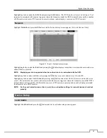
Page 56: ... screen appears Figure 39 Status Event setup screen The Event Status screen displays the status of the DVR s systems and inputs Events will be highlighted and related channels or events will flicker for five seconds when detected Alarm In Motion Video Loss Video Blind Audio and Text In will be highlighted when each event is detected based on the settings you made in the Alarm In Motion Video Loss ...

Page 57: ... Bad or N A depending on storage conditions Good The storage condition is normal Bad Data cannot be written on or read from the storage device N A Storage conditions are normal however the S M A R T monitoring is not working or supported NOTE When the storage condition is Bad the Event Status Storage screen displays and you can check the storage condition for details Once the Bad message displays ...

Page 58: ... A user who does not have Covert Camera View authority cannot view video from cameras set to Covert 1 or Covert 2 in both the live monitoring and playback modes PTZ Highlight PTZ and press the button and the PTZ setup screen appears Local Cameras Only Figure 42 Camera PTZ setup screen NOTE You will only be able to set up PTZ devices if the PTZ port is set to RS232 or RS485 Highlight the box in the...

Page 59: ...tup window appears Configure the port s setting based on the PTZ camera manufacturer s instructions Network Camera Highlight Network Camera and press the button and the Network Camera setup screen appears Network Devices Only NOTE Network Camera includes both network cameras and network video transmitters Figure 43 Camera Network Camera setup screen Highlight the Scan box and press the button and ...

Page 60: ...ure to work the network device should be registered on the DVRNS server You can use the domain name instead of IP address if you set up the DNS Server when setting up the Network IP Address Using the IP Address Scan you can search for a network device that cannot be searched for using the Auto Scan LAN mode After selecting the desired scan mode highlighting Search and pressing the button the syste...

Page 61: ...used when changing device settings Highlight the Port Number Setup box and press the button The Port Number Setup screen appears NOTE You will need to get the appropriate Port Numbers for each program Admin Watch Record and Audio from your network administrator Change the numbers by highlighting them and using the Up and Down arrow buttons to increase or decrease the number The factory default Por...

Page 62: ...evice settings Highlighting the box beside Stream Protocol and pressing the button allows you to select the protocol for streaming Highlighting the box beside Record Protocol and pressing the button allows you to select the protocol for recording Highlighting the box beside ONVIF Profile and pressing the button allows you to select a preset ONVIFTM profile Highlighting the Port Number Setup box an...

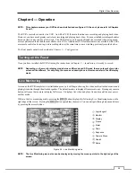
Page 63: ...it is ready to record NOTE Depending on the monitor display mode between HD mode and SD mode the menu layout of monitor screen will be different For simplicity the menus and descriptions in this manual refer to the HD display mode Live Monitoring As soon as the DVR completes its initialization process it will begin showing live video on the attached monitor and playing live audio through the attac...

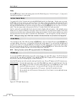
Page 64: ...Display Screen Format and choosing the screen mode displays the cameras in the selected multiview screen mode 2x2 3x2 3x3 4x3 or 4x4 Selecting Screen Format while in 4x4 display format for local cameras enters the display mode for network devices and selecting Screen Format while in 4x4 display format for network devices enters the display mode for local cameras Selecting each display mode is the ...

Page 65: ...mage of the selected camera on the screen It is the same as pressing the ZOOM button Selecting Zoom again in the Camera Menu again exits the Zoom mode Refer to the following Zoom Mode section for details Audio Selecting Camera Menu Audio toggles audio output On and Off Mic Selecting Camera Menu Mic toggles the DVR s audio that is sent to the network device On and Off Color Control Selecting Camera...

Page 66: ...e You can enlarge an area of the video by pressing the ZOOM button For a few seconds after pressing the ZOOM button a rectangle displays on the screen A rectangle shows the area that will be enlarged You can move the rectangle around using the arrow buttons Pressing the button or turning the Jog Dial counterclockwise in the Zoom mode toggles the zoom size between 2x 3x and 4x Exit the Zoom mode by...

Page 67: ... pointer at the bottom of the screen Change the toolbar location by clicking the empty space on the left side of the toolbar and drag it to where you want it located on the screen Use the arrow buttons on the toolbar to pan or tilt the camera in the direction you want The other controls on the toolbar perform as described below Zoom In Out Focus Near Far Iris Open Close Set Load Preset Advanced PT...

Page 68: ...n select the screen mode between 2x2 and 4x4 you want to display on a Spot Monitor Selecting Sequence in the Live Monitoring menu causes the cameras to display sequentially and selecting again stops sequencing on a Spot Monitor Any cameras that are Off have lost video or are set to Covert unless the user has authority to view covert cameras will be excluded from the sequence When the Spot Monitor ...

Page 69: ...ion will be displayed 1 image per second If a user who has Search authority logs into the system the user can view recorded image Once video has been recorded you can view it by pressing the Play Pause button The DVR supports the Triplex function monitoring recording and playing back at the same time Local Cameras Only Pressing the Search Stop button when in one of the multi view formats enters th...

Page 70: ...ed By turning the jog dial clockwise you can play video forward image by image By turning the jog dial counterclockwise you play video backward image by image Shuttle Ring The Shuttle Ring only functions in the Playback mode The Shuttle Ring is spring loaded and returns to the center position when released Turning the ring clockwise plays video forward Turning the ring counterclockwise plays video...

Page 71: ...ime displays the Go to the Date Time screen Move the cursor over the date and time and press the button You can use the Left and Right arrow buttons to highlight the year month day hours minutes and seconds Use the Up and Down arrow buttons to change to the date and time you want to search for video Once you have set the date and time you want press the button Then highlight Go and press the butto...

Page 72: ...Camera OSD or Status OSD On and Off Alarm Selecting Alarm in the Search menu resets the DVR s outputs including the internal buzzer during an alarm It is the same as pressing the ALARM button Panic Selecting Panic in the Search menu starts panic recording of all cameras and selecting again stops panic recording It is the same as pressing the PANIC button Camera Menu Zoom Selecting Camera Menu Zoom...

Page 73: ...ike to see video The Event Log Search screen can also be accessed by pressing the ALARM button unless there is an alarm There is no determined user authority to display the Event Log Search screen however the event video will not be played unless a user with Search authority logs into the system Pressing the button will extract the event video and display the first image of the event Pressing the ...

Page 74: ...eports of motion detection Highlight the box beside Video Loss and press the button You can select the cameras for which you want any reports of lost video Highlight the box beside Video Blind and press the button You can select the cameras for which you want any reports of blind video Highlight the box beside Audio Detection and press the button You can select the cameras for which you want any r...

Page 75: ...ys only the toolbar Selecting the icon in the Compact view mode switches to the Standard view mode and selecting the icon in the Expanded view mode switches to the Standard view mode Selecting or located at the bottom zooms the record table Selecting displays eight hours 1 minute based and selecting displays 24 hours 3 minute based at once To move to earlier or later times that are not shown in th...

Page 76: ...cting in the top left corner exits the Record Table Search screen Motion Search Figure 51 Motion Search screen The Motion Search can be selected from the Search menu while the DVR displays the camera full screen The Motion Search screen displays a list of motion events Use the arrow buttons to highlight the event for which you would like to see video and press the button to display the video assoc...

Page 77: ...order line of the target object If the selected block is placed on the border line the sensitivity of the Museum Search may decrease The zone should be placed or focused on the centre or at least within the outline of targeted object Highlight the box beside Sensitivity and press the button You will be able to select from 1 low sensitivity to 5 high sensitivity Highlight the box beside Min Blocks ...

Page 78: ...s that you want to search for text input Highlight the Text Input Device box and press the button Select your Text Input Device from the list Highlighting the and pressing the button allows you to add a new set of search parameter Set up the desired search parameter Refer to the Appendix Text In Search Examples for further information on setting up search parameters The column can be used to delet...

Page 79: ... pressing the CLIP COPY button on the remote control again will set the ending point of the video to be clip copied by displaying the Clip Copy screen Pressing and holding the MENU button on the front panel or the CLIP COPY button on the remote control for more than three seconds while in the Search mode initiates the One Touch Clip Copy function The last recorded image will be the ending point of...

Page 80: ...ght Verify After Burning and press the button This will toggle between On and Off When this feature is On you can verify that the data is written on the DVD RW properly Highlight Use Site Info and press the button This will toggle between On and Off When this feature is On you can add the site name to the file name for the video you are backing up NOTE When the site name is added to the file name ...

Page 81: ...ght the box beside Printer Model and press the button Selecting PostScript Printer will print images on a PostScript printer connected to the DVR Selecting File Printer will save the current image as a PDF file on an external USB hard disk drive or flash drive NOTE Images saved as PDF files can be printed on any printer connected to your PC Highlight the box beside Paper Size and press the button ...

Page 82: ...start mirroring the two disks will be resynchronized Any data on the destination disk will be erased and the data on the source disk will be copied to the destination disk If the source disk is formatted and has no data the disks will not be resynchronized Resynchronization takes about 40 minutes per each 10GB of capacity After resynchronization is complete disk mirroring writing data on the two d...

Page 83: ...rd disk drive in Windows 98 NOTE Preparing a USB hard disk drive under Windows ME is almost identical to Windows 98 1 Connect the USB hard disk drive to your computer using the USB Cable 2 Turn on your computer The Add New Hardware wizard window will appear 3 Install the device driver for the USB backup device following the instructions provided with your USB hard disk drive 4 If the USB hard disk...

Page 84: ... price mark will be ignored automatically 28th Qty and 40th amount characters including spaces from the left In this case you can enter 17 28 and 40 in each Column box For example if you want to search for Coke with a Qty Quantity of more than 1 and Hotdog with an amount totaling over 8 the following search condition can be set Search Example II 1 2 3 4 5 6 1234567890123456789012345678901234567890...

Page 85: ... x86 32 Bit Service Pack 1 Microsoft Windows 7 x86 32 Bit CPU Intel Pentium III Celeron 600MHz or faster RAM 128MB or higher VGA 8MB or higher 1024x768 24bpp or higher Internet Explorer Version 6 0 or later Start Internet Explorer on your local PC You can run the WebGuard program by entering the following information in the address field http IP address port number The DVR IP address and the WebGu...

Page 86: ...l button Select Enable for the Allow websites to open windows without address or status bars option When running WebGuard in the Microsoft Windows Vista or higher operating system it is recommended to start Internet Explorer with elevated administrator permissions Click the right mouse button on the Internet Explorer icon and select the Run as administrator option from the context menu Otherwise s...

Page 87: ... screen Change Camera Title Changes the camera name Enable Audio Enables audio communication with the remote site When the audio control panel displays click the to send audio to the connected remote site and click the button again to stop sending audio Click the to monitor live audio from the connected remote site through the attached speaker and click the button again stop monitoring live audio ...

Page 88: ...und within the time parameters The Timetable window located at the bottom displays the time information for the image of the date selected on the calendar If more than one video stream in the same time range you can select the video stream you want to search Clicking a specific time displays the image recorded at that time on the screen Selecting the allows you to display an image from a specific ...

Page 89: ...ge In this case you can search overlapping video streams individually by selecting a specific segment For example when the DVR has recorded video from one to five o clock and the user changes the time backward from five to three o clock and then continues recording until six o clock there will be two video streams and segments from three to five o clock You can search overlapping video streams by ...

Page 90: ...mera setup screen highlight the box under the Settings heading and press the button Highlight the Device Remote Setup box and press the button The Device Remote Setup screen appears NOTE The setup menu and options may differ depending on the device model Refer to the network device manufacturer s documentation for correct device settings System Setup Information Displays the device information Mai...

Page 91: ...F Profile Adds or deletes an ONVIFTM profile Video Sets up the video source and encoder The frame rate cannot exceed 15 ips when recording video with the H 264 codec and 4CIF resolution if the device is a network video transmitter Audio Sets up the audio source and encoder Network Setup ...

Page 92: ...for the current network conditions supported only for devices that provide the function Network Protocol Changes the port numbers for the network protocols that are used in the device supported only for the protocols that are used in the device WS Discovery Sets up the WS Discovery function I O Setup I O Sets up the input and output devices PTZ Setup PTZ Sets up the PTZ ...

Page 93: ...Digital Video Recorder 85 Map of Screens ...

Page 94: ...either need to delete video or set the DVR to the Overwrite Mode The icon displays however the DVR is not recording When the DVR is in the Pre Event recording mode the yellow and display when there is no event and the DVR is not recording The red and display when any event occurs and the DVR starts recording While upgrading the system the DVR keeps rebooting and the upgrade fails If the current sy...

Page 95: ...pgrade failed 11 Appending failed 300 Remote connection failed 12 Bad sector 301 Remote network error 13 No executable file 302 Remote upgrade is not authorized 14 Opening executable file failed 303 Saving remote package failed 15 Writing executable file failed 304 Remote upgrade is cancelled by the user 16 Creating image failed 400 USB device mounting failed 17 Burning failed 401 Reading upgrade ...

Page 96: ... p 75 Ohms Secondary Monitor VGA 1 Composite 1 BNC 1 Vp p 75 Ohms SPOT 1 BNC 1 Vp p 75 Ohms Video Resolution Primary Monitor HDMI 1920x1080 1680x1050 1600x900 1440x900 1280x1024 VGA 1920x1080 1680x1050 1600x900 1440x900 1280x1024 Composite 720x480 NTSC 720x576 PAL Secondary Monitor VGA 800x600 Composite 720x480 NTSC 720x576 PAL Composite SPOT 720x480 NTSC 720x576 PAL Record Speed images per second...

Page 97: ...rial Port DB9 P RS485 Serial Port Two connector terminal block IR Port 1 Remote Control USB Port 2 USB 2 0 STORAGE Primary Storage SATA hard disk drive up to 5 up to 4 with an eSATA hard disk drive Secondary Storage eSATA hard disk drive RAID iSCSI hard disk drive RAID Built in DVD RW drive USB hard disk drive or flash drive When installing an internal DVD RW drive connect the SATA I O cable to th...

Reviews: