


14
SN853A
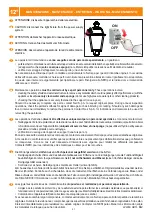
Avvitare l’apparecchio al sostegno con il tubo
fi
lettato G3/4”
(
Fig.
A
).
Nota: può essere
necessario svitare l’apparecchio
fi
no a un mezzo giro per orientarlo.
Stringere con una forza
di 3-4 Nm la vite di blocco posta nel sostegno (1)
(
Fig.
A
)
. Aprire l’apparecchio svitando la
vite
(
Fig.
B
),
ed estrarre dal sostegno circa 50 cm. di cavo
(
Fig.
C
)
. Estrarre il connettore
dall’alimentatore (Fig.
D
), togliere il coperchio fermacavo protettivo svitando le due viti (Fig.
E
).
Misurare il cavo necessario per il collegamento
fi
no alla morsettiera, spellare i cavi e collegarli
alla morsettiera (Fig.
F
).
Screw the device with the threaded tube male (G3/4”) into the support
(
Fig.
A
)
. Note: can be
necessary to unscrew the device up to a half turn for the correct position. Tighten with force of 3
Nm the screw located on the support (1)
(
Fig.
A
)
. Open the top part of the device by slackening
the screw provided
(
Fig.
B
)
, and extract about 50 cm of cable from the support
(
Fig.
C
)
. Extracy
the connector (Fig.
D
) from the compact ballast, remove the protective cover unscrewing the two
screws (Fig.
E
). Measure the cables length needed for connection to terminals, strip the wires
and connect to the terminals (Fig.
F
).
Visser le luminaire au soutien au moyen du manchon
fi
leté G3/4”
(
Fig.
A
).
Note: peut être
nécessaire de dévisser le dispositif jusqu’à un demi-tour pour la position correcte. Visser avec
la force (3 Nm) la vis placée à cet effet sur le soutien (1)
(
Fig.
A
).
Ouvrir la partie supérieure
de l’appareil après avoir dévissé la vis
(
Fig.
B
)
. Extraire environ 50 cm de câble du manchon
(Fig.
C
). Extraire le connecteur (Fig.
D
) du ballast compact, retirez le couvercle de protection en
dévissant les deux vis (Fig.
E
). Mesurer la longueur des câbles nécessaires à la connexion aux
bornes. Dénuder les
fi
ls et connecter aux bornes (Fig.
F
).
Mittels der Gewindemuffe das Gerät an der Halterung anschrauben G3/4” (Abb.
A
). Hinweis: Es
kann notwendig sein, die Vorrichtung zum Abschrauben für die richtige Position zu einer halben
Umdrehung auf. Anziehen mit Kraft von 3 Nm der auf dem Träger be
fi
ndlichen Schraube (1)
(Abb.
A
). Den oberen Teil des Gerätes öffnen, indem die Schraube gelöst wird (Abb.
B
). Etwa 50
cm Kabel aus der Lampenfassung herausziehen (Abb.
C
). Extrahieren Sie den Stecker (Abb.
D
) aus dem kompakten Vorschaltgerät, entfernen Sie die Schutzabdeckung Lösen der beiden
Schrauben (Abb.
E
). Messen Sie die Kabellänge benötigt für den Anschluss an die Klemmen.
Isolieren Sie die Drähte und eine Verbindung zu den Anschlüssen (Abb.
F
).
Atornillen el aparato al brazo de soporte (Fig.
A
), con el manguito roscado G3/4”. Nota: Es
posible que tenga que desatornillar la unidad hasta una media de rotación para orientar.
Atornillen (3 Nm) con el tornillo que hay en el soporte (
1
) (Fig.
A
). Desatornillen los tornillos y
abran la parte superior del aparato
(
Fig.
B
)
. Saquen del manguito unos 50 cm de cable (Fig.
C
).
Extraer el conector (Fig.
D
) de alimentador compacto, retire la tapa de protección a
fl
ojando los
dos tornillos (Fig.
E
). Medir la longitud necesaria para la conexión de los cables a los terminales.
Pelar los cables y conectarlos a los terminales (Fig.
F
).
GB
EE
D
F
I
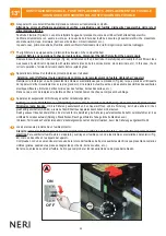
1°
5°
INSTALLAZIONE - INSTALLATION - FIXATION - SOCKEL - ENGANCHE
D
E
L N
M
R
1
A
B
3 Nm
F
G
50 cm
8 mm
CL II
C
Summary of Contents for LIGHT 85 PN853A
Page 24: ...24...