SKS - Steam to Steam Humidifier
Installation Instructions and User Manual
22
Stage 7 – Electrical Control Connections
Fundamentals
About Controls
Placement
A typical humidifier control system includes the following along with the humidifier:
A wall or return duct humidistat
A high limit duct humidistat,
An airflow switch.
Placement of these devices is critical to proper operation of the overall system.
The return duct humidistat must always be located before any outside air intake, in
order to ensure accurate sensing of the air from the humidified space.
Alternatively a room humidistat can be used. The room humidistat must be located
on an inside wall or column. It must not be near any discharge air from supply ducts
or sources of heat or cold.
The airflow switch must be positioned to accurately open on a loss of air flow, to
prevent the humidifier from running when there is no air to absorb humidity.
The high limit humidistat must be positioned far enough, minimum 4.6 m,
downstream of the steam dispersion manifold(s) to prevent over humidification of the
duct that could result in condensation.
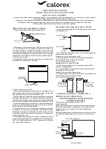
Return SHC80
Humidity sensor
Or room HRO20
humidistat
SHH8 High limit humidistat
High limit SHC80 for
VAV application only
15' minimum
(4.6m)
Air flow switch
Steam dispersion
manifold
Return Air
F
re
s
h
A
ir
Air
(Fig. 20)
Electrical Control
Connections
Neptronic® SKS Humidifier has a modulating control system and requires an
analogue control signal (0-10Vdc, 2-10Vdc, 0-20mA or 4-20mA).
Humidifier
Interlocks
Neptronic® SKS Humidifier has three interlock entries:
P.D. Switch (airflow) contact must be wired on terminal 6
High limit humidistat contact must be wired on terminal 7
A third interlock switch can be wired on terminal 8.
(Fig. 21)
H
i-
L
im
it
h
u
m
id
is
ta
t
F
a
n
P
ro
o
f
2
4
V
A
C
In
te
rl
o
c
k
11
6
5
4
3
2
1
7
8
9
10
C
o
m
m
o
n
12
13
In
p
u
t
s
ig
n
a
ls
F
a
n
&
a
la
rm
s
c
o
n
ta
c
ts
Summary of Contents for SKS-100-SLP
Page 38: ...Notes...
Page 39: ......


