background image

3-14   Disassembly and Reassembly

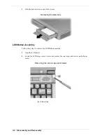
2. 

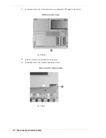
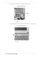
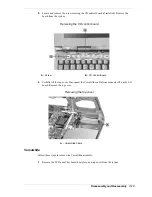
Turn the top cover over and locate the three screws securing the VersaGlide. Remove the
screws.

Removing the VersaGlide screws

A – VersaGlide

B – Screws

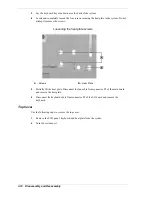
3. 

Slide the VersaGlide assembly away from the top cover tabs and remove the VersaGlide
from the top cover.

CD-ROM Drive

Use the following steps to remove the CD-ROM drive.

1. 

Remove the keyboard.

2. 

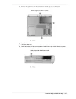
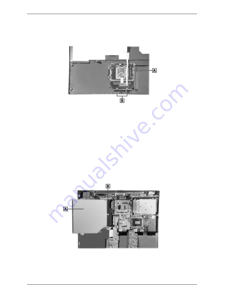
Remove the screw securing the CD-ROM drive.

3. 

Slide the CD-ROM drive out of the system and away from the connector on the main board.

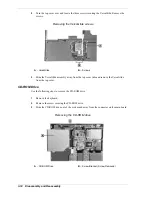
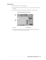
Removing the CD-ROM drive

A – CD-ROM Drive

B – Screw Bracket (Screw Removed)

Summary of Contents for VXI Series

Page 1: ...V VERSA ERSA ERSA ERSA VX VX VX VXI I I I S E R V I C E A N D R E F E R E N C E S E R V I C E A N D R E F E R E N C E S E R V I C E A N D R E F E R E N C E S E R V I C E A N D R E F E R E N C E M A N...

Page 2: ...nce with the terms of the Warranty Statement accompanying each product However actual performance of each such product is dependent upon factors such as system configuration customer data and operator...

Page 3: ...ecting the AC Adapter 2 2 Powering the System On and Off 2 3 Powering On with Windows 2000 2 3 Using the Battery 2 3 Low Battery Power 2 4 Returning the Battery to its Normal State 2 4 Extending Batte...

Page 4: ...98 Environment 2 21 Windows 2000 NT Environment 2 21 Installing the Software 2 22 3 Disassembly and Reassembly Required Tools and Equipment 3 2 Disassembly 3 2 Battery 3 2 Memory Module and Switch Se...

Page 5: ...dling the Battery Pack 6 3 Maintaining the LCD Quality 6 3 7 Troubleshooting Quick Troubleshooting 7 2 Helpful Questions 7 5 8 Getting Services and Support Services and Support Contact Information 8 2...

Page 6: ...ate the notebook Chapter 3 Disassembly and Reassembly provides detailed instructions on how to disassembly the notebook Chapter 4 System Board Layout shows the system boards and the board connectors C...

Page 7: ...ss DMAC DMA controller DOS disk operating system DRAM dynamic RAM DVD digital video disk ECC error checking and correction ECP enhanced capabilities port EDO extended data output EGA Enhanced Graphics...

Page 8: ...mmable peripheral interface PROM programmable ROM QFP quad flat pack RAM random access memory RAMDAC RAM digital to analog converter RAS row address strobe RGB red green blue RGBI red green blue inten...

Page 9: ...ut the NEC Versa VXi Notebook Around the Front of the System Around the Back of the System Around the Left Side of the System Around the Right Side of the System Around the Bottom of the System Intern...

Page 10: ...sk drive diskette drive PC card support and a 24X CD ROM drive a DVD ROM drive or a CD read write drive The NEC Versa VXi comes with Windows 98SE Windows 2000 or Windows NT preinstalled To optimize yo...

Page 11: ...duplicated on the back of the LCD panel to allow viewing when the panel is closed Power and Battery Charging LEDs A Power LED B Battery Charging LED Power LED lets you know that power to the system is...

Page 12: ...systems Password Buttons set a password or personal identification number for security Available on some systems Status LEDs keep you informed of your NEC Versa VXi s current operating status Descrip...

Page 13: ...s D Scroll Lock B Diskette Drive Access E Num Lock C Caps Lock Hard Drive Access lights when the NEC Versa VXi accesses the hard disk drive CD ROM drive or DVD ROM drive Diskette Drive Access lights w...

Page 14: ...igure Keyboard panel A Keyboard B NEC VersaGlide Base unit A Speakers D Audio Ports B IR Port E Volume Control C Microphone Keyboard standard QWERTY key layout Models shipped outside of the U S are eq...

Page 15: ...e right control key to support IBM 327X connections Fn F3 Toggles the video mode between LCD only CRT only Simultaneous mode and TV out Fn F4 Sets standby power management mode on in Windows NT In Win...

Page 16: ...Ctrl key and type the letter c Key combinations work specific to the application you are running Cursor Control keys Cursor control keys let you position the cursor on the screen where you want On th...

Page 17: ...e AC power source using the AC adapter that comes with your system Keep the system connected to AC power whenever possible to keep the battery pack and internal CMOS battery charged Parallel Port Use...

Page 18: ...udio CDs Diskette Drive A 3 5 inch 1 44 MB diskette drive comes installed in the NEC Versa Hard Disk Drive An internal hard disk drive comes installed in the NEC Versa The disk drive is upgradeable Ar...

Page 19: ...or depending on the model Lithium Ion Li Ion battery Battery Release Latch Slide the latch to the other end and hold it While holding the latch slide the battery bay outwards to remove the battery Me...

Page 20: ...n on the system s configuration for example date time drives and memory The CMOS battery charges when your NEC Versa is connected to AC power The CMOS battery may discharge completely if the NEC Versa...

Page 21: ...2 System Configuration and Setup Power Sources for Your NEC Versa BIOS Setup Updating the BIOS NEC Utilities Application and Driver CD...

Page 22: ...dapter whenever a wall outlet is nearby Keep the adapter connected whenever possible The AC adapter charges the battery when it is connected whether the NEC Versa is powered on or off Do not attempt t...

Page 23: ...skbar click Start Settings and Control Panel 2 Double click Power Options 3 Select the Hibernate tab 4 Check the box to enable Hibernate support 5 Click OK and close Control Panel Using the Battery Th...

Page 24: ...ries or using a combination of very old and new batteries can deteriorate battery and equipment performance Turn off power to the system after use Keeping system power on can degrade battery performan...

Page 25: ...the bay Slide the battery into the bay until securely locked into place Installing the battery 5 Turn over the system Charging the Battery When the system is on or off or in Suspend mode and the AC a...

Page 26: ...rheats or emits a foul odor Keep the battery dry and away from water Keep metal objects away from battery terminals Metal objects in contact with the terminals can cause a short circuit and damage If...

Page 27: ...your system with a password balance your performance needs with power conservation Access the BIOS utility at power on Just press F2 when the following prompt appears Press F2 to Enter BIOS Setup Whe...

Page 28: ...that move the cursor and select parameters Options that are grayed out are not available for the current selection Using Keys The following table lists the BIOS Setup keys and their functions BIOS Set...

Page 29: ...p Main Menu and press Enter Select Yes and press Enter Standard CMOS Setup Use the Standard CMOS Setup screen to view the System Time System Date and to modify drive parameters and related settings St...

Page 30: ...void infection by some virus types Advanced CMOS Setup Use the Advanced CMOS Setup to set the following functions Advanced CMOS Setup Parameter Default Setting Alternate Setting s Video Out Type NTSC...

Page 31: ...sign a password to allow or restrict access to the hard disk drive contents Internal HDD Password Enables or disables the HDD password Password Protection Your NEC Versa supports a password for system...

Page 32: ...etup highlight and select the System Security Setup 2 Highlight Assign HDD Password and press Enter The system prompts you to enter a master password 3 Enter a master HDD password and press Enter The...

Page 33: ...cating that the drive is locked Next the Security Setup screen appears requiring the user to enter the master password to unlock the drive Highlight the HDD password line and enter the master password...

Page 34: ...Up Alarm Disabled Enabled Resume Alarm Time 2 Off Set time in 5 min increments when Wake Up Alarm is set Intel SpeedStep technology Automatic Disabled Battery Optimized 1 Available when power savings...

Page 35: ...to File LCD Suspend Allows you to suspend the system when the LCD panel is closed Suspend Option Specifies either Suspend or Save to File STF as the default power management mode Automatic STF Enable...

Page 36: ...DD Disabled Floppy CD DVD Try Other Boot Devices Yes No 1 Bootable device when set to IDE hard drive Only one IDE device is bootable Quick Boot Specifies whether or not the system performs all tests d...

Page 37: ...the internal hard drive Serial Port Disables the port or changes its address assignment Parallel Port Parallel Mode Disables or reassigns the parallel port and selects a parallel port mode IR Serial P...

Page 38: ...fixes to the current system BIOS Your authorized NECC dealer or NECC Support Services representative can help you determine this To update the system BIOS you must Obtain the BIOS Update Prepare the B...

Page 39: ...d automatically loads the utility A message similar to the following appears The NEC BIOS Update Utility should not be used to modify the BIOS in a Versa system which is docked If your Versa is docked...

Page 40: ...ions The window below the options list displays a description of each option when the option is highlighted The Launch button initiates a selected option when clicked The More Info button provides an...

Page 41: ...ll applications drivers utilities Internet browsers and the online NEC Info Center Launching the Application and Driver CD Follow these procedures to launch the Application and Driver CD using NEC Cus...

Page 42: ...hted software category or application driver etc Install Clicking the Install button installs the selected software Exit Clicking the Exit button closes the Application and Driver CD dialog box Once t...

Page 43: ...3 Disassembly and Reassembly Required Tools and Equipment Disassembly Reassembly...

Page 44: ...the system follow the disassembly instructions that follow When disassembling the system unit follow these general rules Turn off the system and disconnect all power and all options including the AC...

Page 45: ...lide the battery out of the system Removing the battery A Battery Release Latch Memory Module and Switch Settings Use the following steps to remove the memory module and access the switch settings 1 P...

Page 46: ...the CD ROM drive The following list identifies each switch setting and its function Switch 1 Password override The default setting is OFF If you forget your password and cannot access the data on your...

Page 47: ...ard disk drive follow these steps 1 Locate the drive access panel on the left side of the system Open the panel using the notch Opening the panel A Drive Access Panel B Notch 2 Remove the screw that s...

Page 48: ...e system Removing the disk drive LED Button Assembly Follow these steps to remove the LED Button assembly 1 Open the LCD panel 2 Locate the LCD hinge covers Locate and remove the screw caps and screws...

Page 49: ...inge covers A Hinge Cover 4 Slide the LED button assembly slightly to the right and lift away from the system Removing the LED button assembly A LED Button Assembly LCD Panel Use the following steps t...

Page 50: ...cate and remove the two bottom screws securing the LCD panel to the system Removing the screws A Screws 4 Turn the system over and open the LCD panel 5 Locate and remove the left and right hinge screw...

Page 51: ...e LCD panel screws A Screws 7 Pull the LCD panel up and away from the system Keyboard and Heat Plate Follow these steps to remove the keyboard and heat plate 1 Remove the LCD panel from the system 2 P...

Page 52: ...ws Loosening the heat plate screws A Screws B Heat Plate 5 Partially lift the heat plate Disconnect the fan cable from connector P5 of the main board and remove the heat plate 6 Disconnect the keyboar...

Page 53: ...t screws on the bottom that secure the top cover to the system Removing the bottom screws A Screw 4 Turn the system over 5 Locate and remove the one screw inside the hard disk drive bay that secures t...

Page 54: ...embly 6 Locate and remove the one screw on the top that secures the top cover Removing the top screw A Screw 7 Locate and remove the screw securing the LED board Remove the board from the system Remov...

Page 55: ...the CD control board A Screw B CD Control Board 9 Partially lift the top cover Disconnect the VersaGlide cable from connector P8 on the I O board Remove the top cover Removing the top cover A VersaGl...

Page 56: ...the VersaGlide assembly away from the top cover tabs and remove the VersaGlide from the top cover CD ROM Drive Use the following steps to remove the CD ROM drive 1 Remove the keyboard 2 Remove the scr...

Page 57: ...te and top cover from the system 2 Locate and remove the screw securing the audio board 3 Carefully disconnect the audio board from connector P7 on the main board by lifting the audio board Disconnect...

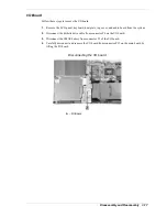
Page 58: ...s to remove the DC DC board 1 Remove the LCD panel keyboard heat plate and top cover from the system 2 Carefully disconnect and remove the DC DC board from connectors P9 and P10 on the main board by l...

Page 59: ...op cover and audio board from the system 2 Disconnect the diskette drive cable from connector P6 on the I O board 3 Disconnect the CMOS battery from connector P1 of the I O board 4 Carefully disconnec...

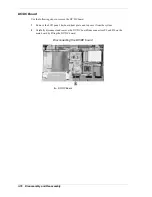
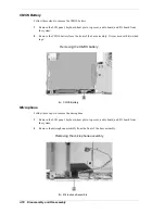
Page 60: ...CMOS battery from the front of the base assembly It is secured with two sided tape Removing the CMOS battery A CMOS Battery Microphone Follow these steps to remove the microphone 1 Remove the LCD pan...

Page 61: ...p cover audio board and I O board from the system 2 Locate and remove the two screws securing the diskette drive to the base assembly Removing the diskette drive screws A Screws B Diskette Drive 3 Lif...

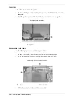
Page 62: ...t of the base assembly There are two speakers Removing the speaker A Speaker Kensington Lock Latch Use the following steps to remove the Kensington lock latch 1 Remove the LCD panel keyboard heat plat...

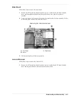
Page 63: ...2 Locate and remove the four screws that secure the main board to the base assembly Use the needle nose pliers to remove the three hex screws Removing the main board screws A Hex Screw C Main Board B...

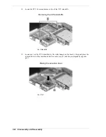
Page 64: ...CPU standoffs Removing the CPU standoffs A Standoffs 3 Locate pin 1 on the CPU identified by the white triangle on the board Align and place the actuation block of the insertion extraction tool over p...

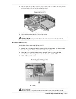
Page 65: ...the die Pentium III Removal Follow these steps to remove the Pentium III CPU 1 Remove the LCD panel keyboard heat plate top cover audio board I O board diskette drive Kensington lock latch and main b...

Page 66: ...n the main board over 3 Remove both memory modules if present 4 Locate and remove the four screws that secure the PC card assembly to the main board Removing the PC card screws A Screws B Main Board b...

Page 67: ...4 System Board Layout Audio Board DC DC Board I O Board Main Board...

Page 68: ...4 2 System Board Layout This following figures show the system boards and connector locations Audio Board A Connector P3 DC DC Board A Connector P1 B Connector P2...

Page 69: ...D Connector P2 B Connector P3 back side E Connector P1 C Connector P6 F Connector P8 Main Board A Connector P17 F Connector P5 B Connector P15 G Connector P4 C Connector P10 H Connector P7 D Connector...

Page 70: ...5 Illustrated Parts Breakdown Illustrated Parts Breakdown Parts List...

Page 71: ...5 2 Illustrated Parts Breakdown Illustrated Parts Breakdown...

Page 72: ...rd Sub Assembly 136 275691 551 A 9 Keyboard Heat Plate Assembly 136 246094 001 A 10 Microphone Cable 808 130515 212A 11 Battery Li Ion NiMH 804 021626 002A 804 021627 002A 12 Bottom Base Sub Assembly...

Page 73: ...edStep 650 MHz Pentium III with SpeedStep 700 MHz Pentium III with SpeedStep 802 143937 502 A 802 143937 503 A 802 143937 505 A 802 143607 502 A 802 143607 503 A 802 143607 702 A 802 143607 703 A 802...

Page 74: ...6 Preventive Maintenance Cleaning the Notebook Exterior Cleaning the Notebook Interior Protecting the Disk Drive Handling the Battery Pack Maintaining the LCD Quality...

Page 75: ...ior When servicing the inside of the notebook remove dust and other foreign particles from inside the system unit as follows 1 Remove the top cover and keyboard using the disassembly procedures discus...

Page 76: ...ive shock and vibration Do not expose the battery pack to direct sunlight moisture chemical compounds or extreme heat Do not disassemble the battery pack Do not use the battery pack to power other dev...

Page 77: ...7 Troubleshooting Quick Troubleshooting Helpful Questions...

Page 78: ...e installed VGA driver is correct and resolution is set according to the LCD size and type Check if the LCD panel is connected properly Replace the main board LCD screen does not show display Check if...

Page 79: ...o the other slot Replace the memory module Replace the main board External keyboard or PS 2 mouse does not work Check if the keyboard or mouse is connected properly Check if the PS 2 Y cable is being...

Page 80: ...enabled in BIOS Setup Check if File Sharing and the Computer name are both set properly Check if the Infrared Monitor is activated Check if the IR ports on both systems are blocked or obstructed Check...

Page 81: ...o the computer Is the battery fully charged Is the computer turned on and the Power LED activated Is the LCD display switched to the external monitor Are all cables and devices connected properly and...

Page 82: ...8 Getting Services and Support Services and Support Contact Information NECC Web Site NECC FTP Site Email Fax to Support Services NECC Support Services...

Page 83: ...can also be used to answer your questions and help solve any problems you may have with your system should that ever be necessary NECC Web Site If you have a modem or a network board you can access t...

Page 84: ...nse from the appropriate technical person Desktop Monitor Notebook You should provide as much specific information about your questions as possible Also if you are sending a fax please include your vo...

Page 85: ...our system s name model number serial number and as much information as possible about your system s problem before calling For outside the U S or Canada please contact your local NECC office or deale...

Page 86: ...9 Specifications System Components Connector Locations Memory Map Interrupt Controllers...

Page 87: ...he Celeron or 256 KB L2 cache Pentium III Read Only Memory ROM 512 KB flash ROM with boot block Calendar Clock Year month day hour minute second maintained by internal back up battery Input Output I O...

Page 88: ...ype II or one Type III PC card 5 V or 3 3 V interface LCD Display Panel depending on the model 12 1 inch Thin Film Transistor TFT cold cathode fluorescent tube CCFT backlit Super VGA color 13 3 14 1 i...

Page 89: ...ady CD G and CD Plus 8X DVD ROM Drive Burst Transfer Rate 16 67 MB sec PIO Multiword DMA Read Rate CD 3600 KB sec max DVD 8115 KB sec max Average Access Time DVD 270 ms Random 480 ms Full Stroke CD 18...
Page 90: ...ration 0 2G read 0 1G write Mini PCI Modem K56 Flex compatible V 34 extended rate protocol V 90 compliant Enhanced AT command set Class 1 and 2 Fax protocols Built in speaker with software controllabl...

Page 91: ...s System Width 12 in 307 mm Depth 9 9 in 252 mm Height 1 6 in 40 mm max 44 mm Weight 6 6 lbs 3 0 kg 12 1 inch LCD 6 8 lbs 3 1 kg 13 3 inch LCD 7 0 lbs 3 2 kg 14 1 inch LCD Recommended Environment Oper...

Page 92: ...table shows the system s connector locations Connector Locations Connector Location P1 Audio Board P2 Audio Board P1 I O Board P5 I O Board P6 I O Board P8 I O Board P2 Main Board P5 Main Board P7 Ma...

Page 93: ...te protection The following table shows the system s memory map System Memory Map Memory Space Size Function 00000000h 0009FFFFh 640 KB System Memory 000A0000h 000BFFFFh 128 KB Video Memory 000C0000h...

Page 94: ...imer IRQ01 Keyboard IRQ02 Cascade IRQ03 IR IRQ04 Serial Port IRQ05 CardBus Mini PCI Sound Video IRQ06 Diskette Drive IRQ07 Parallel Port IRQ08 Real time Clock IRQ09 USB IRQ10 Video IRQ11 Available IRQ...

Page 95: ...t Output System A collection of primitive computer routines usually burnt into ROM that controls the real time clock keyboard disk drives video display and other peripheral devices bit Binary digit Th...

Page 96: ...rning on the power If power is already on the process means to turn off the computer and turn it on again A cold boot reinitializes all devices crt Cathode Ray Tube A type of display screen used in de...

Page 97: ...function I input output I O The process of transferring data between the computer and external devices IDE Intelligent Drive Electronics A hard disk drive type that has controller electronics built i...

Page 98: ...ze greater design flexibility and reduced cost for mobile platforms mode A method of operation for example the NEC Versa operates in either normal or power saving modes modem MOdulator DEModulator A d...

Page 99: ...pheral Input or output device not under direct computer control A printer is a peripheral device pixels Picture elements Tiny dots that make up a screen image port Provides the means for an interface...

Page 100: ...bit at a time serial printer A printer with a serial interface software Programs that run on a computer such as operating systems word processors and spreadsheets SpeedStep technology Intel s SpeedSt...

Page 101: ...nd a graphics resolution of 640 by 480 pixels volatile memory Storage media that loses its data when system power is turned off Standard memory and memory that you add to the NEC Versa are volatile me...

Page 102: ...DC board removing 3 16 Dip switch settings 3 4 diskette drive removing 3 19 Diskette drive 1 12 2 10 specifications 9 4 E Entering BIOS setup 2 7 Establishing passwords 2 11 F Function key combination...

Page 103: ...ard 3 15 Celeron 3 21 hard disk 3 5 I O board 3 17 keyboard and heat plate 3 9 LED Button assembly 3 6 main board 3 21 microphone 3 18 PC card assembly 3 24 Pentium III 3 23 speakers 3 20 VersaGlide 3...

Page 104: ...t or relocate the receiving antenna Increase the separation between the equipment and receiver Connect the equipment to an outlet on a circuit different from the one to which the receiver is connected...

Page 105: ...nufacturer Discard used batteries according to the manufacturer s instructions Il y a danger d explosion s il y a replacement incorrect de la batterie Remplacer uniquement avec une batterie du m me ty...

Page 106: ...NEC Computers Inc 15 Business Park Way Sacramento CA 95828 www nec computers com 819 200669 000 05 2000...

Reviews: