background image


 3-10   Setting Up and Using the Software

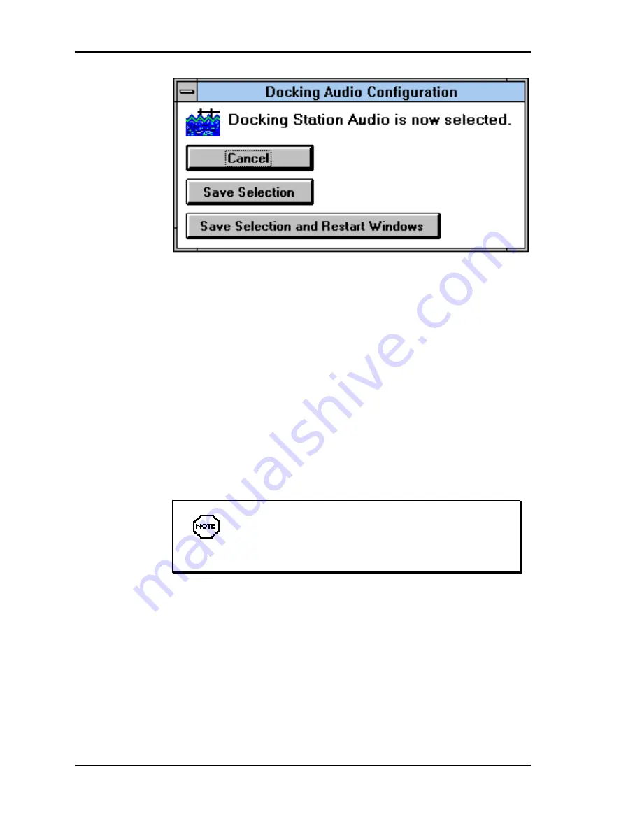
 Audio switcher dialog box

5. 

The three buttons shown give you the following options.

n


Cancel — Click this button to return to the Welcome
screen without making or saving any changes. The
sound system that was active when you opened the
utility remains active.

n


Save Selection — Click this button to change the
audio sound system to be used the next time Win-
dows restarts. This button saves the new configura-
tion but does not engage it until Windows restarts.


The new sound system selection is not active

until you restart Windows.

n


Save Selection and Restart Windows — Click this
button to activate the chosen audio system immedi-
ately. The system restarts Windows and activates the
sound system.


Summary of Contents for VERSA 4000 BATTERY CHARGER WITH AC ADAPTER

Page 1: ...warranted in accordance with the terms of the Warranty Statement accompanying each product However actual performance of each such product is dependent upon factors such as system configuration customer data and operator control Since implementation by customers of each product may vary the suitability of specific product configurations and applications must be determined by the customer and is no...

Page 2: ...ng an NEC Versa on the docking station n Chapter 3 explains setting up the software to use your docking station and NEC Versa together n Chapter 4 details how to add options to the docking station These options include expansion boards and various types of drives n Chapter 5 directs you through connecting peripheral devices like an external keyboard mouse monitor printer and audio options n Append...

Page 3: ...tions that can cause per sonal injury or harm CAUTION Cautions indicate situations that can damage sys tem hardware or software Notes give particularly important information about the topic being discussed n Names of keys are printed as they appear on the key board for example Ctrl Alt or Enter n Text that you must type or keys that you must press are presented in bold type For example type dir an...

Page 4: ...EC Versa Series Docking Station 4000 and NEC Versa operation n Your NEC Versa user s guide n The Microsoft Windows and MS DOS Operating Sys tem documentation that came with your NEC Versa n Manuals and setup instructions for any devices that you are installing in or connecting to the docking station ...

Page 5: ...t 1 12 Storage Environment 1 12 Docking Station 4000 Care 1 13 Precautions 1 13 Routine Care 1 14 Battery Charging 1 14 2Docking Undocking the NEC Versa Hardware Setup 2 1 Connecting the Power Cable 2 2 Preparing the NEC Versa for Docking 2 4 Docking the NEC Versa 2 6 Undocking the NEC Versa 2 11 Normal Undocking 2 11 Emergency Undocking 2 13 3Setting Up and Using the Software Plug and Play System...

Page 6: ...ation File 3 16 Switching between Configurations 3 17 The SCSI Configuration Driver 3 18 Using the Driver 3 18 Modifying the CONFIG SYS File 3 19 Quick Start 3 22 4Adding Options Cover Removal 4 2 Cover Replacement 4 4 Expansion Boards 4 6 Precautions 4 7 Slot Locations 4 7 Installation 4 7 Removal 4 12 Data Storage Devices 4 14 Preparing the Drive 4 14 Installing Drives in the Front Bay 4 15 Remo...

Page 7: ...crophone 5 7 Headphones or Speakers 5 8 Headphones 5 8 Speakers 5 8 Line In Line Out 5 9 Line In 5 9 Line Out 5 9 Parallel Devices 5 9 Serial Devices 5 11 External SCSI Devices 5 12 A Specifications BPin Assignments Keyboard and Mouse Ports B 1 COM Port B 2 Printer Port B 3 Monitor Port B 4 AT Interface Connectors B 5 Expansion Port B 9 CSolving Problems Problem Checklist C 1 Troubleshooting C 2 I...

Page 8: ...vi Contents Error No table of contents entries found ...

Page 9: ...king station supports the newest Plug and Play boards as well as older non Plug and Play legacy boards The sleek ergonomic docking station design makes it pleas ant to look at and easy to use Its innovative docking mechanism insures secure and easy docking and undocking This chapter describes the features and capabilities of the docking station WHAT S IN THE BOX Carefully unpack the shipping carto...

Page 10: ...llowing features which are described in greater detail in the sections that follow n Support for full Windows 95 configuration and Plug and Play options n Support and on board connectors for both SCSI and IDE interfaces n An electronic docking mechanism that makes docking and undocking easier than ever n A CRT base that lets you put an external monitor on top of the docking station to save premium...

Page 11: ... 5FG monitor Do not exceed the weight limit Doing so can damage the unit n A 3 position lock to ensure that your NEC Versa is not undocked without authorization n Stereo speakers for outstanding quality sound n Full SoundBlaster compatibility n Ports on the back of the unit for connecting external peripherals like a PS 2 style keyboard PS 2 style mouse printer monitor and much more n LEDs on the f...

Page 12: ...ng mechanism makes docking and undocking easier than ever After setting up the hardware all you do is position the NEC Versa on the docking station and give it a gentle push towards the connector The mechanism reaches out grasps the NEC Versa and completes the docking process n Expansion Connector This connector attaches the NEC Versa and the docking station interface board n Air Vents These allow...

Page 13: ...ts as a Resume switch if the NEC Versa is in Suspend mode n Eject Button Pressing the eject button undocks the NEC Versa All you have to do is remove the laptop n Stereo Speakers These speakers provide excellent sound quality Use your applications software to control the volume and balance n External Bay Access These front panels are removable to allow access to drives installed in the bays n Manu...

Page 14: ...ay systems or the Eject button Set the key lock to this po sition for normal use This setting secures the docking lever and prevents accidental damage to the locking mechanism It also minimizes any chance of data loss Locked secures your NEC Versa to the docking station This setting keeps the NEC Versa from being removed from the docking station You must use the key to unlock the unit before remov...

Page 15: ... Green If docking or undocking is unsuc cessful due to an error or jam the LED blinks Steady Red Once the NEC Versa docking process completes successfully the LED lights a steady red n Hard Disk Drive Access lights green when a hard disk drive in either the NEC Versa or the docking station is being accessed n Diskette Drive Access lights green when a diskette in the NEC Versa is accessed n NEC Ver...

Page 16: ...Keylock Status Lights Green indicates that the lock is locked Blinks Green if the keylock is in the locked posi tion and you issue a software eject command or press the Eject button Back Features Features on the back of the docking station are shown in the following figure Descriptions follow the figure Features on the back of the docking station ...

Page 17: ...t lets you connect a serial de vice such as a printer or modem to the docking station n Expansion Slot Covers protect the expansion board slots when no boards are installed If you add expansion boards to the docking station these covers are removed n Power Port lets you connect the power cord to the docking station and AC power n Voltage Selection Switch lets you select the correct voltage to use ...

Page 18: ...eadphones or exter nal speakers Line In lets you use another audio system like a CD player as an input source Use a cable to con nect to the Line Out port on the other audio system to record or play Line Out lets the docking station act as an input source for another audio system Connect this port to a Line In port on another audio system to play or record ...

Page 19: ...docking station Internal Features Internal NEC Docking Station 4000 features are shown next The following figure shows the docking station with its cover removed Descriptions of internal features follow the figure Internal features n Board Expansion Slots three full size ISA expansion slots n External Access Bay allows the installation of up to two 5 1 4 inch half height drives n Hard Disk Drive B...

Page 20: ...uidelines n Select a flat sturdy surface like a desktop or table so you have access to both the front and back of the unit n Choose an area away from extremely warm or cold sur roundings direct sunlight excessive dust vibration shock or moisture Operating Environment Use the docking station in a location that meets the follow ing environmental conditions n Temperature 41 F to 95 F 5 C to 35 C n Hu...

Page 21: ...tem perature of the unit and damage its parts n Do not use or store the docking station in dusty environments n Do not use or store the docking station near chemicals n Do not cover the air vents or put anything near enough to them to block air circulation n Avoid excessive vibration or shock Dropping the docking station or knocking it over can cause serious damage n Keep the docking station away ...

Page 22: ...with a mild detergent Never use a strong solution or spray cleaner on any part of the unit n Check the docking station regularly for loose material such a paper books magazines that might block the air vents and prevent proper air circulation n Keep food and liquids away from the docking station and NEC Versa BATTERY CHARGING The docking station charges the battery installed in your NEC Versa as l...

Page 23: ...docking station n Preparing the NEC Versa and connecting it to the dock ing station n Powering on the NEC Versa The first time you use the NEC Docking Sta tion 4000 you must set system parameters on the NEC Versa hard disk You must set docking station parameters on every hard disk drive that you plan to use with the docking station These procedures are described in Chapter 3 This chapter also desc...

Page 24: ...and AC power before docking the computer The power cable that came with the docking station pro vides power to the docking station and the NEC Versa Connect the docking station power cable as follows 1 Position the docking station on a flat surface close to an AC outlet 2 Attach one end of the cable to the AC power port on the docking station 3 Attach the other end to a properly grounded wall outl...

Page 25: ...the electronic docking mechanism to work Pressing the main power button on the back of the unit pro vides the necessary power Powering on the docking station CAUTION Disconnecting the power cable turning off power or experiencing a power outage while running the docking station and NEC Versa can result in a sys tem crash If this occurs see the instructions in Emergency Undocking later in this chap...

Page 26: ...re docking For example the NEC Versa 4000 with Windows 95 running is a Plug and Play system n If you have a non Plug and Play system turn off system power before docking Non Plug and Play systems include the UltraLite Versa NEC Versa E NEC Versa M NEC Versa P or NEC Versa V Make sure your system is in Suspend mode or powered off as appropriate before docking If the NEC Versa is in Active mode or p...

Page 27: ...n See Connecting the Power Cable for details The Docking LED should be a steady green which indi cates that it is ready for docking Docking LED 4 On the back of the NEC Versa open the expansion port cover and slide it underneath the expansion port Check that all other NEC Versa port covers are closed Opening the NEC Versa expansion port cover ...

Page 28: ...em power off This method works for all NEC Versa models that support docking n Warm Docking with NEC Versa power on and the system in Suspend mode This procedure can be used with NEC Versa 4000 systems with the Windows 95 operating system Use the following steps to dock your NEC Versa 1 Locate the expansion connector on the docking station Locating the expansion connector ...

Page 29: ...e connector Push either against the center of the computer or push with equal pressure against the left front and right front of the NEC Versa Keep the NEC Versa straight If the computer is pushed at an angle it does not dock properly To prevent connector damage the docking mecha nism will not start to dock if the expansion connec tors are not aligned properly If this occurs adjust the NEC Versa p...

Page 30: ... and try again A blinking Docking LED indicates that something went wrong with the docking sequence due to an er ror or hardware failure If the LED continues to blink after you re attempt docking call your authorized NEC service representative 4 To lock your NEC Versa onto the docking station insert the key into the lock and turn it The Docking Lock pro vides three lock settings that let you contr...

Page 31: ... locking mechanism Locked secures your NEC Versa to the docking station This setting keeps the NEC Versa from being removed from the docking station You must use the key to unlock the unit before removing the NEC Versa If no computer is docked and the key is in the Locked position no one else can dock their computer on the docking station The Keylock LED lights green when the unit is locked Lockin...

Page 32: ...r the first time you do not always need to use the power button to power on your sys tem If the docking station remains plugged in and the main power switch on the back of the unit stays turned on the NEC Versa automatically powers on after docking If you turn off AC power through the main power switch or by unplugging the docking station you must use the power button the first time you dock your ...

Page 33: ...otor jam Normal Undocking Undock your NEC Versa as follows 1 Check the status of your NEC Versa power n If you have an NEC Versa 4000 with Windows 95 put your system into Suspend mode or turn off sys tem power before undocking n If you have an UltraLite Versa NEC Versa E NEC Versa M NEC Versa P or NEC Versa V turn com puter power off before undocking To power off the NEC Versa press the power butt...

Page 34: ...docking station To use Windows 95 software to undock the NEC Versa locate the Eject icon on the screen and click The soft ware puts your NEC Versa into Suspend mode and initi ates the undocking sequence If the NEC Versa does not eject properly us ing the front panel Eject button go to the next sec tion Emergency Undocking 5 Once the connection is broken pull the NEC Versa for ward and remove it fr...

Page 35: ...ergency undocking procedure to undock the NEC Versa 1 If possible turn off NEC Versa power or put the system into Suspend mode a half moon is displayed on the LCD panel If the NEC Versa cannot be powered off or put into Suspend mode turn off the main power switch on the back of the docking station before continuing 2 Turn the docking station key to the Unlock position 3 Close the NEC Versa LCD pan...

Page 36: ...2 14 Docking Undocking the NEC Versa 5 Pull the NEC Versa forward and lift it out of the dock ing station Emergency undocking ...

Page 37: ... Plug and Play systems and their setup requirements go to the section Non Plug and Play System Setup n If you are extremely familiar with software setup pro grams and the NEC Versa family of computers you may find the Quick Start section at the end of this chapter all you need to get started PLUG AND PLAY SYSTEM SETUP Plug and Play systems like the NEC Versa 4000 with the Windows 95 operating syst...

Page 38: ... NON PLUG AND PLAY SYSTEM SETUP Some NEC Versa models do not support Plug and Play options because of software or hardware restrictions To use options in a docking station with non Plug and Play systems or options you must configure the option according to the NEC Versa and option requirements See your NEC Versa user s guide and the option guide Setting up the software to use your NEC Docking Stat...

Page 39: ... not docked you can specify the original NEC Versa configuration called Mobile Setting up dual configurations requires the following n Checking the level of MS DOS installed on your NEC Versa n Running the Docking Station 4000 Setup utility You must perform software setup on each hard disk that you plan to use with the Docking Station 4000 MS DOS Version Check the MS DOS version installed on your ...

Page 40: ...ion 4000 and power on 2 Boot into Windows if Windows is not already opened Type win and press Enter to open Windows 3 Close any Windows applications that may be running for example CardView or the NEC Battery Gauge 4 Insert the first Docking Station 4000 Setup diskette into the drive 5 From the Windows Program Manager access the File pull down menu and select Run 6 Type a winstall and press Enter ...

Page 41: ...m does not require that the drivers be loaded the system prompts you to restart Windows At the prompt click the Restart Windows button This completes software setup for your system If you want to load the ESS drivers for any reason insert audio diskette 1 into the drive From the Win dows File menu select the Run command Enter a setup exe and press Enter to load the drivers n If your system needs t...

Page 42: ...the Install Software button to install the audio software at the next prompt n Software installation Press Enter or click OK to accept the default directory PCAUDIO for loading the audio soft ware Press Enter again to create the directory Choose Complete Installation for the type of installation to follow At the prompt insert Audio Applications diskette 2 into the drive and press Enter 10 Click Re...

Page 43: ...itcher Utility for more information n Some programs run from MS DOS instead of Windows Use the information under Using DOS Based Programs to enable and control Docking Station 4000 sound from MS DOS applications Choosing a Configuration After setting up the Docking Station 4000 software your NEC Versa boot up differs from its original procedure The new boot up sequence lets you choose which config...

Page 44: ...king station other than the Docking Station 4000 This option may not appear depending on your system configuration Using the Audio Switcher Utility Follow these steps to use the NEC Versa M Audio Switcher utility If the Docking Station 4000 sound system is selected and the NEC Versa is not docked run this utility to switch to the NEC Versa M sound system Otherwise you cannot use your system audio ...

Page 45: ... fol lowing appears Audio Switcher welcome screen 3 From the screen click the button for the audio system that you want to use n The laptop button selects the NEC Versa audio n The Docking Station button selects the Docking Sta tion 4000 audio 4 A dialog box similar to the following appears and identi fies the sound system selected ...

Page 46: ...ened the utility remains active n Save Selection Click this button to change the audio sound system to be used the next time Win dows restarts This button saves the new configura tion but does not engage it until Windows restarts The new sound system selection is not active until you restart Windows n Save Selection and Restart Windows Click this button to activate the chosen audio system immedi a...

Page 47: ...tup utility When using applications that run from MS DOS you may need to change these sound settings The following two utilities let you adjust the speaker vol ume and change the DMA and IRQ addresses n ESSVOL EXE allows you to increase or decrease the volume of the sound coming from the Docking Station 4000 n ESSCFG EXE allows you to change DMA and IRQ settings if your application requires that y...

Page 48: ... volume c changed the CD volume s changes the synthesizer volume n A number between 0 and 15 as the new setting The following example decreases the master volume to 3 and increases the wave volume to 14 ESSVOL V 3 W 14 When you finish using your DOS based application you do not need to reset the volume settings for Windows At boot up Windows specifies its own settings Changing IRQ and DMA Settings...

Page 49: ...nd call the appli cation manufacturer Docking Station default settings are as follows n Board type SoundBlaster Pro Compatible n IRQ 5 n DMA 1 If your application indicates that it requires special settings proceed as follows 1 From the DOS prompt type the following and press Enter to change to the DS4000 directory cd DS4000 2 Display the current IRQ and DMA settings by typing the following and pr...

Page 50: ...vers If it does load the drivers according to the instructions that come with the option Configure non Plug and Play options according to the instructions that came with the options and those in the NEC Versa user s guide If you install non Plug and Play devices in a Plug and Play system you must still configure the option according to its requirements For some options like a second IDE drive or d...

Page 51: ... Systems Although earlier DOS versions cannot support multiple configuration files you can work round the situation Doing so requires that you create two separate sets of system files with different names Each set of system files contains different configuration information for your system to use For example one set of files contains the docking station configuration The other set of files contain...

Page 52: ...ess Enter to begin formatting 4 Once the diskette is formatted enter a volume name and press Enter or press Enter to skip naming the volume 5 Type N when prompted to format another diskette and press Enter 6 While the diskette is still in the drive type the following and press Enter to copy the CONFIG SYS file to the diskette copy c config sys a 7 Type the following and press Enter to copy the AUT...

Page 53: ... the DOS prompt and press Enter copy CONFIG SYS CONDS SYS Switching between Configurations Once you copy the system files as described in the pre ceding section you can switch between configurations as follows You only need to follow this procedure when you want to change to the other configuration The configuration you choose will remain the default until you change it 1 While your system is stil...

Page 54: ...y systems like the NEC Versa 4000 take control of this port and its settings However if your system is a non Plug and Play system you may need to specify some settings for the port The SCSI Configuration driver included with the Setup utility provides a means for specifying port settings If you have a Plug and Play system you do not need to use the SCSI Configuration driver You system automaticall...

Page 55: ...g or disabling the port n Command line switches or options are processed in the sequence in which they appear If you use the reboot op tion make sure it is the last option to appear on the command line Modifying the CONFIG SYS File Modify the CONFIG SYS file as follows For details about editing the CONFIG SYS file and saving the changes see your MS DOS documentation 1 Add the following as the firs...

Page 56: ...ss Selection x 0 I O address 140 15Eh default 1 I O address 340 35Eh n Ix SCSI IRQ Enable Disable x 0 enables IRQ default 1 disables IRQ n Qx SCSI IRQ Selection x 0 Use IRQ 10 default 1 Use IRQ 11 4 Use IRQ 14 5 Use IRQ 15 n Dx SCSI DMA Enable Disable x 0 enables DMA default 1 disables DMA n Mx SCSI DMA Selection x 5 Use DMA 5 6 Use DMA 6 7 Use DMA 7 default ...

Page 57: ...00 scsictrl sys S0 The following example disables the SCSI port and then re boots the system using the system port device c ds4000 scsictrl sys S0 R0 The next example enables the SCSI port and specifies an alternate IRQ device c ds4000 scsictrl sys S1 Q4 Do not use a drive connected to this port as the boot drive for your operating system Due to the system configuration routine booting from this p...

Page 58: ...that may be running 4 Insert the first Docking Station 4000 Setup diskette into the drive 5 From the Windows Program Manager access the File pull down menu and select Run 6 Type a winstall and press Enter or click OK 7 Respond to the utility as prompted 8 When Setup is complete reboot your system when prompted For some systems the Setup utility only loads the online docking station user s guide If...

Page 59: ... AT style ISA expansion boards Installing these options require that you remove the docking station cover Once the options are installed you must re place the cover before using the docking station This chapter provides the information you need to remove and replace the docking station cover install expansion boards and add optional drives Before installing an option or expansion board in the dock...

Page 60: ...n the Docking Lock to the Locked position for easier cover removal and replacement This setting also keeps the manual docking lever in place while removing and replacing the cover CAUTION Failure to set the Docking Lock to Locked before removing or replacing the cover can cause damage to the locking mechanism 2 Remove the CRT Base from the docking station 3 Locate and turn the cover latch on the b...

Page 61: ...he cover latch 4 Pull the cover forward to clear the expansion connector Clearing the expansion connector CAUTION When disassembling the docking station be careful not to drop anything into it Doing so can damage the unit ...

Page 62: ...ng station Removing the cover COVER REPLACEMENT Once your options are installed replace the docking station cover as follows 1 Turn the Docking Lock to the Locked position for easier cover removal and replacement This setting also keeps the manual docking lever in place while removing and replacing the cover ...

Page 63: ...e locking mechanism 2 Align and lower the cover over the front of the docking station Make sure the cover clears the expansion connector CAUTION Be careful not to catch any wires or cables when re placing the cover Move cables aside if they look like they may be pinched or squeezed when you re place the cover Positioning the cover ...

Page 64: ... back of the docking station Make sure the expansion connector and docking sensor protrude through the opening in the cover Replacing the cover 5 Slide the cover all the way onto the docking station 6 Turn the cover latch on the back of the docking station to secure the cover Securing the cover ...

Page 65: ...move expansion boards from the shipping material very carefully Static discharge can damage board components Take the following precautions when handling boards n Avoid carpets in cool dry areas n Before handling a board discharge any static electricity by touching a grounded metal object n Always hold a board by its edges Avoid touching the components on the board Slot Locations Slot locations fo...

Page 66: ...ollows n Disconnect and remove the NEC Versa from the docking station n Turn off and unplug the docking station n Disconnect any peripheral devices connected to the docking station n Remove the docking station cover See Cover Re moval earlier in this section for information on re moving the cover n Position the docking station so you have access to the side where the expansion slots are located ...

Page 67: ...g into the docking sta tion Doing so can damage the unit 2 Locate and remove the screw that attaches the slot cover to the docking station Removing the slot cover screw 3 Remove the slot cover 4 Locate the expansion slot connectors inside the docking station ...

Page 68: ...in sert it into the slot If installing a full size board fit the board into the guide at the front of the docking station Aligning the board edge and connector 6 Press the board firmly until it is securely seated in the connector You may have to rock the board side to side ...

Page 69: ...teps 2 through 7 to install a second or third ex pansion board 9 Once you install the boards continue as follows n To add drives continue to the next section Data Storage Devices n If you have no more options to install replace the docking station cover as described in Cover Re placement earlier in this chapter ...

Page 70: ...ation n Turn off and unplug the docking station n Disconnect any peripheral devices connected to the docking station n Remove the docking station cover See Cover Re moval earlier in this section for information on re moving the cover n Position the docking station so you have access to the side where the expansion slots are located CAUTION Be careful not to drop anything into the docking sta tion ...

Page 71: ...move the screw that attaches the board to the support bracket Removing the screw 3 Hold the board by its edges and pull the board You may need to rock the board side to side to dislodge it from its connector Removing the board ...

Page 72: ...e docking station support only two diskette drives Therefore if you have more than two diskette drives installed in the NEC Versa and docking station you can only access two of them Some storage devices require that you provide a signal cable For example to install a SCSI device you need to purchase an optional SCSI signal cable Follow the instructions in the next section to prepare your drive for...

Page 73: ... Attaching power and signal cables to the drive n Finishing up reinstalling the drive cage with the drive in the docking station These procedures are described next Removing the Drive Cage Prepare the docking station for drive installation by remov ing the drive cage as follows WARNING Make sure docking station power is off the NEC Versa is not docked peripheral devices are discon nected and cable...

Page 74: ...ing drive cage screws 3 Slide the drive cage towards the back of the unit Make sure the holes on the bottom of the cage clear the tabs on the bottom of the docking station chassis 4 Lift the drive cage up and out of the system ...

Page 75: ... the drive to the drive cage as follows Before attaching the drive to the cage make sure that any switches on the drive are set properly See the guide that came with the drive for switch setting information 1 Align the front of the drive with the front of one of the bays in the drive cage ...

Page 76: ...drive is seated on the guides within the cage Sliding the drive into the cage 3 Locate the screw holes on the side of the drive cage and align them with the screw holes on the side of the drive 4 Using the screws that came with the drive secure the drive to the drive cage ...

Page 77: ...r and position the red edge of the cable as shown in the figures Taking care not to bend any pins press the cable connector firmly onto the pins 1 Place the drive cage close to the docking station for easy access to the connectors on the docking station interface board 2 Look in the package of cables that came with the dock ing station and locate drive power cable ...

Page 78: ...4 20 Adding Options Drive power cable 3 Connect the power cable to the docking station interface board Connecting the power cable ...

Page 79: ...ug and Play SCSI devices purchase a cable that comes with a terminated connector You can pur chase this optional cable from your NEC dealer n For diskette drives Look in the package of cables and find the disk ette drive signal cable Diskette Drive Cable Connect the diskette drive signal cable to the docking station interface board as shown in the following figure ...

Page 80: ...own Routing the diskette drive signal cable Position the red edge of the signal cable as shown in the following figure and connect the cable to the drive Connect a large or small power cable connector to the drive connector size depends on the drive you are installing Power connectors are keyed to fit only one way ...

Page 81: ...Adding Options 4 23 Connecting the diskette drive signal cable n For IDE drives Look in the package of cables and find the IDE signal cable IDE signal cable ...

Page 82: ...gure Route the cable over the side of the interface board and snake it behind the LED bracket as shown Routing the signal cable If you are installing an IDE device with audio features like a CD ROM reader connect the audio cable as follows Locate the audio cable in the bag of cables that came with the docking station ...

Page 83: ...Adding Options 4 25 Audio Cable Attach the audio cable to the docking station in terface board Route the cable over the side of the interface board and snake it behind the LED bracket as shown ...

Page 84: ...nectors are keyed to fit only one way Connect a large or small power cable connector to the drive connector size depends on the drive you are installing Power connectors are keyed to fit only one way The audio cable comes with two connectors Pick the one that is appropriate for your drive type ...

Page 85: ...you must purchase an optional SCSI cable If you are installing Plug and Play SCSI devices purchase a cable that comes with a terminated connector You can pur chase this type of cable from your NEC dealer Locate your optional SCSI cable It should look similar to the one shown in the following figure ...

Page 86: ...Adding Options Optional SCSI signal cable Locate the SCSI cable connector on the docking station interface board Connect the SCSI signal cable to the interface board Connectors are keyed to fit only one way ...

Page 87: ... Connecting the SCSI cable to the interface board If you are installing a SCSI device with audio features like a CD ROM reader connect the audio cable as follows Locate the audio cable that came with the dock ing station ...

Page 88: ...4 30 Adding Options Audio cable Attach the audio cable to the docking station in terface board Route the cable over the side of the interface board and snake it behind the LED bracket as shown ...

Page 89: ...ce to next connector on the cable Do not skip connectors when attaching more than one SCSI de vice Connect the cables to the back of the drive See the documentation that came with the drive exact connector locations Locations vary depending on model The audio cable comes with two connectors Pick the one that is appropriate for your drive type ...

Page 90: ...n as follows 1 Locate the tabs on the bottom of the docking station chassis 2 Position the drive cage a little behind the tabs and lower it into the unit 3 Slide the drive cage forward until the tabs slide into the matching holes on the bottom of the drive cage 4 Replace the two screws that secure the drive cage in the docking station ...

Page 91: ...external access re move the drive slot cover from the docking station cover as follows n Locate the drive slot cover tabs inside the docking station cover n Gently push the tabs out until you can release the cover n Remove the slot cover and store it in a safe place for possible future use ...

Page 92: ...d in Cover Replacement Hard Disk Drives Installing a hard disk drive involves the following steps n Preparing the hard disk drive n Setting your hard disk drive to slave or master as appro priate n Installing the drive n Connecting cables n Finishing up This section describes how to install a hard disk drive in the internal hard disk drive bay in the docking station ...

Page 93: ...rive that requires a controller board install the board as de scribed in Expansion Boards See the documentation that comes with the drive for specific cabling instructions Before starting the installation check the following n The interface of your hard disk must match the interface of the hard disk controller For example an IDE hard disk requires an IDE hard disk controller If you are installing ...

Page 94: ...ly as the first master or second slave drive Check the jumper settings on the drive before beginning the installation procedure Only one drive can be identified as the master drive If you plan to use the NEC Versa IDE drive when docked set the docking station IDE drive to the slave settting Installing the Drive Follow these instructions to install a hard disk drive in the internal drive bay of the...

Page 95: ...y Locating the internal drive bay 3 Align the hard disk drive so that its cable connectors face the front of the docking station Make sure the screw holes on the hard disk drive face the drive bracket in the docking station 4 Insert the drive into the drive bay ...

Page 96: ...4 38 Adding Options Aligning and installing the drive 5 Align the screw holes on the drive with those on the bracket ...

Page 97: ...ttach the disk drive to the guide Attaching the drive to the bracket 7 To continue go to the appropriate cabling section n See Attaching IDE Drive Cables for IDE drive in stallations n See Attaching SCSI Drive Cables for SCSI drive installations ...

Page 98: ... the accessories bag that came with your docking station IDE Signal Cable 2 Connect the IDE cable to the IDE connector on the docking station interface board The connectors are keyed to fit in only one position 3 Route the cable over the edge of the interface board and snake the cable behind the LED bracket ...

Page 99: ...connector with the connector on the hard disk drive 5 Taking care not to bend any pins press the cable con nector firmly onto the pins on the drive The connectors are keyed to fit in only one position 6 Locate the power cable that came in the cable accesso ries bag ...

Page 100: ...Options Connecting the power cable to the interface board 7 Connect the cable to the interface board Power connec tors are keyed to fit in only the correct position Connecting the power cable to the interface board ...

Page 101: ...nstall replace the docking station cover as described in Cover Replacement 10 Proceed as follows n If you have a Plug and Play system simply dock the NEC Versa and reboot your system The NEC Versa automatically detects the new drive n If you do not have a Plug and Play system run Auto Setup to set your new configuration ...

Page 102: ...al SCSI cable If you are installing Plug and Play SCSI drive purchase a cable that comes with a terminated connector You can purchase this type of cable from your NEC dealer 1 Locate the SCSI cable connector on the docking station interface board The cable should look similar to the one shown in the following figure Optional SCSI cable ...

Page 103: ... on the SCSI cable to the connector on the board The connectors are keyed to fit in only one position Attaching the SCSI cable 3 Align the cable connector with the hard disk drive con nector as shown The connectors are keyed to fit only one way ...

Page 104: ...when attaching more than one SCSI de vice 4 Taking care not to bend any pins press the cable con nector firmly onto the pins The connectors are keyed to fit in only the correct position 5 Attach the appropriate power cable connector to the power connector on the hard disk Power connectors are keyed to fit only in the correct position Attaching the SCSI cable to the drive ...

Page 105: ...ed in Cover Replacement 7 Proceed as follows n If you have a Plug and Play system simply dock the NEC Versa and reboot your system The NEC Versa automatically detects the new drive n If you do not have a Plug and Play system run Setup or the Automatic Configuration Utility to set your new configuration ...

Page 106: ... system configuration set with your NEC Versa setup utility also called the ACU Parameters and configuration files are discussed in Chapter 3 Setting Up and Using the Software External options that you can connect include the following n External monitor n External keyboard and mouse n External audio peripherals including Headphone and external speakers Microphone External sound sources connected ...

Page 107: ... docking station Never place an external monitor or any other heavy object directly on the docking station or NEC Versa without the CRT base Doing so can damage the unit The CRT base weight limit is 56 2 lb 25 5 kg equivalent to an NEC MultiSync 5FG monitor Do not exceed the weight limit Doing so can damage the unit Use the following steps to connect an external monitor to the docking station If y...

Page 108: ...rsa display panel is closed and secured 2 Lower the CRT base onto the docking station Lowering the CRT base into place 3 Carefully set the external monitor on the CRT base or desk 4 Attach the 15 pin connector on the signal cable to the monitor port on the docking station ...

Page 109: ... of the power cable into the appropriate port on the back of the monitor 7 Plug the other end of the power cable into a properly grounded wall outlet 8 Power on the external monitor 9 Power on the docking station Always power on the monitor before powering on the NEC Versa Otherwise the system may not recognize the monitor type ...

Page 110: ...e NEC Versa power and docking station power are off 2 Locate the keyboard port on the back of the docking sta tion 3 Insert the keyboard cable connector in the port Connecting an external keyboard 4 Turn on power to the NEC Versa and docking station EXTERNAL MOUSE The NEC Docking Station 4000 lets you attach an external mouse When a mouse is connected the NEC Versa mouse trackball or NEC VersaGlid...

Page 111: ...a and docking station EXTERNAL AUDIO OPTIONS The docking station provides various audio ports on the back of the unit for connecting audio devices such as head phones microphones and external speakers When you plug in these audio attachments they use the sound capa bilities in the docking station If you install an optional sound board in the docking station use the input and output jacks on the ba...

Page 112: ...ng station audio ports Microphone For the best results NEC recommends that you use an omnidirectional monaural microphone that has an electric condenser See Appendix A Specifications for recommended microphone specifications To connect a microphone to the docking station insert the microphone jack into the microphone port ...

Page 113: ... is not set to maxi mum A maximum volume setting can cause injury to your ears When you connect headphones the internal docking station speakers are disabled To connect headphones insert the headphone jack into the headphones port Speakers When you connect external speakers the internal docking station speakers are disabled Connect external speakers as follows 1 Set up your speakers according to t...

Page 114: ...dio system like your home stereo To play or record from the docking station use a cable to connect to the Line In port on the other audio system to the docking station Line Out port Parallel Devices To connect a parallel printer you need a parallel printer ca ble with a male 25 pin connector for the docking station and for most parallel printers a Centronics compatible 36 pin connector Use the fol...

Page 115: ... 3 Secure the printer cable as follows n Lock the connector to the printer with the connector clips n Secure the cable to the docking station with the screws provided Connecting a parallel device 4 Connect the power cable to the printer 5 If you are having trouble communicating with the paral lel device reboot your system ...

Page 116: ...rements depend upon the device Before connecting an RS 232C device to your docking station make sure the device is set up cor rectly Follow the setup instructions that come with the option 1 Turn off and unplug the docking station and any external options connected to it 2 Make sure that any power to the RS 232C device is off and the power cable is unplugged 3 Connect the RS 232C cable to the seri...

Page 117: ... Check that the SCSI device is set up properly See the documentation that came with the device to verify switch and jumper settings 2 Turn off and unplug the docking station and any external devices connected to it 3 Locate the external SCSI connector on the back of the docking station 4 Squeeze the tabs on the side of the SCSI cable connector and attach the SCSI cable to the back of the docking s...

Page 118: ...Connecting Peripheral Devices 5 13 6 Reconnect any options that you disconnected Turn on the device and the docking station Connecting an external SCSI device ...

Page 119: ...mpatible Sound Subsystem ESS 1688 Sound Chip High quality stereo speakers Stereo right and left channels On board mixer Internal power amp for sound system controlled by external control panel separate from mixer Wave Audio compatible A D D A converter Up to 44 KHz sampling frequency 16 bit CD quality Input Output Facilities n Docking connector n Serial RS 232C 9 pin connector n Parallel EPP 25 pi...

Page 120: ...noise ratio 50 dB min 1 Pa 1 KHz A curve Frequency response 20 16 000 Khz Connector 3 5 mm phone plug Contact ground sleeve tip output and D C bias Ring NC n Headphone external port accepts standard headphone or external speaker jack n Line In external port for connecting stereo amplifier external CD player or another input source lets the docking station act as an output device n Line Out externa...

Page 121: ...7 5 in 190 5 mm n Width 16 25 in 412 75 mm n Depth 17 25 in 438 15 mm n Weight 20 lb 9 07 kg Environmental Requirements Operating Requirements n Temperature 41 F to 95 F 5 C to 35 C n Humidity 20 to 80 noncondensing Storage Requirements n Temperature 4 F to 122 F 20 C to 50 C n Humidity 10 to 85 noncondensing Provided Software n NEC Docking Station 4000 Setup utility includes ESS sound drivers and...

Page 122: ...n mini DIN female ports The keyboard and mouse connectors are male connectors Keyboard and mouse ports KEYBOARD MOUSE PORT PIN ASSIGNMENTS PIN SIGNAL I O FUNCTION 1 KBDATA MOUSEDATA I O Keyboard data Mouse data 2 NC Not connected 3 GND Ground 4 5V Power 5 KBCLK MOUSECLK I O Keyboard clock Mouse clock 6 GND Ground B ...

Page 123: ...ort pin assignments are as follows COM port COM PORT PIN ASSIGNMENTS Pin Function 1 Carrier Detect 2 Receive Data 3 Transmit Data 4 Data Terminal Ready 5 Signal Ground 6 Data Set Ready 7 Request to Send 8 Clear to Send 9 Ring Indicator ...

Page 124: ...ows Printer port PRINTER PORT PIN ASSIGNMENTS Pin Function 1 Strobe 2 Data Bit 0 3 Data Bit 1 4 Data Bit 2 5 Data Bit 3 6 Data Bit 4 7 Data Bit 5 8 Data Bit 6 9 Data Bit 7 10 Acknowledge 11 Busy 12 PE 13 Select 14 Auto Feed XT 15 Error 16 Initialize 17 Select In 18 25 Ground ...

Page 125: ...R PORT PIN ASSIGNMENTS Pin Function 1 Red 2 Green 3 Blue 4 Monitor ID bit 2 not used 5 Ground 6 Red return ground 7 Green return ground 8 Blue return ground 9 Key no pin 10 Sync return ground 11 Monitor ID bit 0 not used 12 Monitor ID bit 1 not used 13 Horizontal sync 14 Vertical sync 15 Not used ...

Page 126: ... O A3 SD6 I O A4 SD5 I O A5 SD4 I O A6 SD3 I O A7 SD2 I O A8 SD1 I O A9 SD0 I O A10 I O CH RDY I A11 AEN O A12 SA19 I O A13 SA18 I O A14 SA17 I O A15 SA16 I O A16 SA15 I O A17 SA14 I O A18 SA13 I O A19 SA12 I O A20 SA11 I O A21 SA10 I O A22 SA9 I O A23 SA8 I O A24 SA7 I O A25 SA6 I O A26 SA5 I O A27 SA4 I O A28 SA3 I O A29 SA2 I O A30 SA1 I O A31 SA0 I O ...

Page 127: ...5 5 Vdc Power B6 DRQ2 I B7 12 Vdc Power B8 OWS I B9 12 Vdc Power B10 GND Ground B11 SMEMW O B12 SMEMR O B13 IOW I O B14 IOR I O B15 DACK3 O B16 DRQ3 I B17 DACK1 O B18 DRQ1 I B19 REFRESH I O B20 CLK O B21 IRQ7 I B22 IRQ6 I B23 IRQ5 I B24 IRQ4 I B25 IRQ3 I B26 DACK2 O B27 TC O B28 BALE O B29 5 Vdc Power B30 OSC O B31 GND Ground ...

Page 128: ... O C6 LA19 I O C7 LA18 I O C8 LA17 I O C9 MEMR I O C10 MEMW I O C11 SD08 I O C12 SD09 I O C13 SD10 I O C14 SD11 I O C15 SD12 I O C16 SD13 I O C17 SD14 I O C18 SD15 I O D1 MEM CS16 I D2 I O CS16 I D3 IRQ10 I D4 IRQ11 I D5 IRQ12 I D6 IRQ15 I D7 IRQ14 I D8 DACK0 O D9 DRQ0 I D10 DACK5 O D11 DRQ5 I D12 DACK6 O D13 DRQ6 I D14 DACK7 O ...

Page 129: ...B 8 Pin Assignments AT INTERFACE PIN ASSIGNMENTS CONT D Pin Signal I O D15 DRQ7 I D16 5 Vdc Power D17 MASTER I D18 GND Ground ...

Page 130: ... GND 31 12 V CHG 5 GND 32 12 V CHG 6 GND 33 Docking Station Detect 1 7 GND 34 AGND 8 GND 35 AGND 9 GND 36 AGND 10 GND 37 TC 11 GND 38 BALE 12 GND 39 IOCHCK 13 GND 40 IOCHRDY 14 GND 41 AEN 15 GND 42 SBHE 16 GND 43 MEMR 17 GND 44 MEMW 18 GND 45 RESET DRV 19 GND 46 OWS 20 GND 47 SMEMR 21 GND 48 SMEMW 22 GND 49 IOR 23 GND 50 IOW 24 12 V CHG 51 IOCS16 25 12 V CHG 52 PC Detect 26 12 V CHG 53 HDD Access ...

Page 131: ...A21 63 12 V sys 92 LA20 64 12 V sys 93 LA19 65 12 V sys 94 LA18 66 12 V sys 95 LA17 67 CRT red 96 FD Write Protect 68 CRT green 97 FD Disk Change 69 SA17 98 FD Read Data 70 SA18 99 FD Index 71 SA19 100 CRT Blue 72 MEMCS16 101 CRT Hsync 73 Refresh 102 SD8 74 PR Data Strobe 103 SD9 75 PR ACK 104 SD10 76 PR Busy 105 SD11 77 PR PE 106 SD12 78 PR Select 107 SD13 79 PR Auto Feed 108 SD14 80 PR Error 109...

Page 132: ...elect 0 148 DACK2 120 FD Motor 0 149 DACK5 121 SD7 150 DACK7 122 SD6 151 FD Drive Select 1 123 SD5 152 FD Motor 1 124 SD4 153 FD Write Data 125 SD3 154 SA15 126 SD2 155 SA13 127 SD1 156 SA11 128 SD0 157 SA9 129 N C 158 SA7 130 N C 159 SA5 131 N C 160 SA3 132 N C 161 SA1 133 CRT VSYNC 162 N C 134 CLK1 163 N C 135 PR D2 164 N C 136 PR D4 165 N C 137 PR D6 166 PR D0 138 IRQ3 167 PR D1 139 IRQ5 168 PR...

Page 133: ...l 171 IRQ4 185 PC Power Control 172 IRQ6 186 SA16 173 IRQ9 187 SA14 174 IRQ11 188 SA12 175 IRQ14 189 SA10 176 DRQ0 190 SA8 177 DRQ2 191 SA6 178 DRQ5 192 SA4 179 DRQ7 193 SA2 180 DACK1 194 SA0 181 DACK3 195 N C 182 DACK6 196 N C 183 PC Power Good 197 N C 184 Battery Charge 198 N C ...

Page 134: ... Check the items in the following list if you cannot get the NEC Docking Station 4000 to work If these do not help continue to the Troubleshooting section of this appendix n Check that the NEC Versa is connected properly to the docking station n Check that NEC Versa power is turned on and that the NEC Versa is not in a power saving state such as Sleep mode n Verify that the electrical outlet to wh...

Page 135: ...xer n Pressing the power button does not turn on the docking station Check that the AC power cable is connected properly to the docking station and a wall outlet Check the wall outlet by plugging in another electrical device such as a lamp Check that the Power Button on the back of the docking station is in the On position The vertical bar should be pressed down n No sound can be heard from the do...

Page 136: ...EC Versa manually n You added an optional SCSI drive and now you have an IRQ conflict If your system is a non Plug and Play system follow the instructions in Chapter 3 for using the SCSI configuration driver IF YOU NEED HELP If you have a problem with your Docking Station 4000 first review the checklist and problems listed previously If you still have a problem call the NEC Technical Support Cente...

Page 137: ...onfiguration utility ACU 4 35 Setup utility 4 35 Configuring Non Plug and Play Options 3 14 Configuring Plug and Play Options 3 14 Connecting a Parallel Device 5 9 Connecting a Serial Device 5 11 Connecting an External Keyboard 5 5 Connecting an External Mouse 5 5 Connecting an External SCSI Device 5 12 Connecting Audio Options 5 6 Connecting the Power Cable 2 2 Cover 4 2 removal 4 2 replacement 4...

Page 138: ...Attachment 5 2 External Speakers 5 8 F Features 1 2 back 1 8 front 1 4 internal 1 11 left side 1 4 H Hard Disk Drive Installation 4 34 Hard Disk Drive Interface 4 35 Hardware Setup 2 1 Headphones 5 8 I IDE Drive Cabling 4 23 If You Need Help C 3 Indicator LEDs A 2 Internal Features 1 11 K Keyboard Connector Pin Assignments B 1 L LEDs 1 6 Line In 5 9 Line In Line Out Ports 5 9 Line Out 5 9 Lock Set...

Page 139: ...aring to Dock 2 4 Printer Port Pin Assignments B 3 Problem Checklist C 1 Provided Software A 3 R Removing the Drive Cage 4 15 Replacing the Drive Cage 4 32 Routine Care 1 14 Running the Setup Utility 3 4 S SCSI Device External 5 12 SCSI Drive Cabling 4 27 SCSI Drives 4 36 Serial Device Connection 5 11 Setting Up the Hardware 2 1 Setting Your NEC Versa for Docking 2 4 Setup Utility Use 3 4 Single C...

Page 140: ...Index 4 T Troubleshooting C 2 U Undocking 2 11 Using the Audio Switcher Utility 3 8 Using the Eject Button 2 11 Using the Undocking Lever 2 13 W Warm Docking Method 2 6 ...

Reviews: