background image

3-30     Options


NOTE:

  Do not remove the 5 1/4-inch blank

panel when installing a hard disk drive.


The 3 1/2-inch hard disk drives must be mounted
in a 5 1/4-inch bracket.

Minitower Blank Panel Removal

Remove the front panel assembly from the minitower chassis as follows.

1. 

Remove the minitower cover as previously described.

2. 

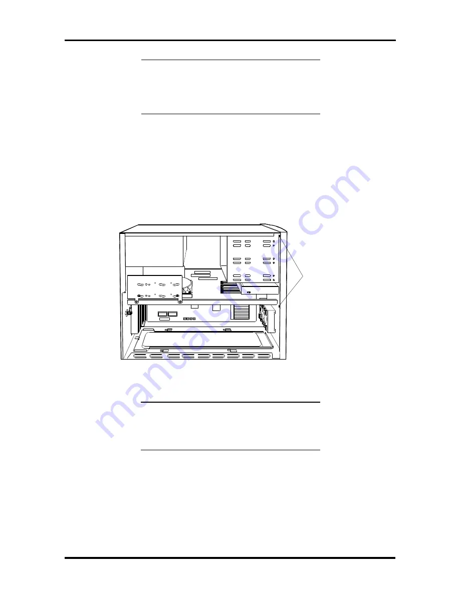
Remove the four screws holding the front panel to the system; two screws on
each side(see Figure Section 3-34).

 Figure Section 3-34   Removing the Front Panel Screws


NOTE:

  If installing a hard disk in the 5 1/4-inch

slot, do not remove the slot cover. Otherwise
store the slot cover for reuse if the device is
removed.

3. 

Release the blank panel tabs and remove the blank panel from the metal cover
plate (see Figure Section 3-36).


2 of 4
Screws

Summary of Contents for POWERMATE P60D - SERVICE

Page 1: ...ranted in accordance with the terms of the Warranty Statement accompanying each product However actual performance of each such product is dependent upon factors such as system configuration customer data and operator control Since implementation by customers of each product may vary the suitability of specific product configurations and applications must be determined by the customer and is not w...

Page 2: ...rrupt Controller 1 9 Video Controller 1 10 Video Memory 1 10 ISA PCI Bus Backboard 1 12 ISA Bus 1 12 PCI Local Bus 1 12 PCI Auto Configuration 1 12 Parallel Interface 1 13 Serial Interface 1 14 Indicator Panel 1 14 Power Supply 1 15 Diskette Drive 1 15 Hard Disk Drive 1 15 Keyboard 1 15 Section 2 Setup and Operation Unpacking and Repacking 2 1 Setup 2 1 Desktop Setup 2 2 Minitower Setup 2 5 System...

Page 3: ...ting 3 9 System Board Options 3 10 OverDrive Processor Installation 3 11 OverDrive Processor Troubleshooting 3 13 SIMM Memory Installation 3 13 SIMM Upgrade Path 3 14 SIMM Installation 3 17 SIMM Upgrade Kit Troubleshooting 3 18 Video DRAM Chip Installation 3 19 Video DRAM Chip Troubleshooting 3 20 Optional 5 1 4 Inch Slot Devices 3 21 5 1 4 Inch Diskette Drive 3 21 5 1 4 Inch Diskette Drive Settin...

Page 4: ...itor 3 40 Connecting the Monitor 3 41 Front Control Panel 3 43 Rear Control Panel 3 44 NEC SVGA Monitor Troubleshooting 3 45 Section 4 Maintenance and Troubleshooting Maintenance 4 2 Routine Checks 4 2 System Unit 4 2 Keyboard 4 3 Mouse 4 4 Troubleshooting 4 5 Error Messages 4 5 Diagnosing and Solving Problems 4 7 Beep Codes 4 11 BIOS Update Utility 4 12 Recovery Mode 4 13 Section 5 Desktop Repair...

Page 5: ...skette Drive Removal 6 15 Power Supply Removal 6 17 ISA PCI BUS Backboard Removal 6 19 System Board Removal 6 20 Illustrated Parts Breakdown 6 22 Appendix A Connector Pin Assignments Serial Interface Connectors A 3 Parallel Interface Connector A 4 VGA Interface Connector Pin Assignments A 5 Speaker Connector Pin Assignments A 5 Power Supply Connectors A 6 Keyboard and Mouse Connectors A 6 Power La...

Page 6: ...the Desktop Cover 3 2 3 3 Minitower Cover Screws 3 3 3 4 Removing the Minitower Cover 3 4 3 6 Desktop Expansion Slots 3 6 3 7 Inside Expansion Slot Screw 3 6 3 8 Removing the Inside Expansion Slot Bracket 3 7 3 9 Minitower Expansion Slots 3 8 3 10 System Board Option Sockets 3 10 3 11 PGA OverDrive Socket Lever 3 11 3 12 OverDrive Processor Alignment 3 12 3 13 3 1 2 Inch Drive Bracket Screws 3 17 ...

Page 7: ...xpansion Slot Screw 5 4 5 5 Removing the Expansion Slot L Bracket 5 5 5 6 ISA PCI Bus Backboard Screws 5 5 5 7 3 1 2 Inch Drive Bracket Screws 5 6 5 8 3 1 2 Inch Diskette and Hard Disk Drive Screws 5 7 5 9 Indicator Panel Connectors 5 8 5 10 Power Button Tabs 5 9 5 11 Speaker Screw 5 10 5 12 SIMM Socket 5 11 5 13 5 1 4 Inch Device Screws 5 12 5 14 5 1 4 Inch Device Cage Screws 5 13 5 15 Power Butt...

Page 8: ...tor J12 Pin Assignments A 6 List of Tables 1 1 System Board Chips 1 4 1 2 System Memory Map 1 6 1 3 I O Address Map 1 7 1 4 Interrupt Level Assignments 1 9 1 5 Video Resolutions and Frequencies 1 10 1 6 Parallel Port Addressing and Interrupts 1 13 1 7 Serial Port Addressing and Interrupts 1 14 2 1 Standard CMOS Setup Parameters 2 11 2 2 Advanced CMOS Setup Parameters 2 12 2 3 Peripheral Management...

Page 9: ...scriptions A 2 A 2 Video Connector P8 Pin Assignments A 5 A 3 Speaker Connector P6 Pin Assignments A 5 A 4 Keyboard P1 And Mouse P2 Connector Pin Assignments A 6 A 5 Power Lamp Connector P5 Pin Assignments A 6 A 6 Hard Disk Drive Lamp Connector P7 Pin Assignments A 7 A 7 Fan Connector P5 Pin Assignments A 7 A 8 Reset Button Connector P5 Pin Assignments A 7 A 9 Diskette Drive Connector P13 Pin Assi...

Page 10: ...odes for computer A procedure is provided for logging onto the NEC Bulletin Board and obtaining the latest the Flash ROM BIOS A CMOS recovery mode procedure is also included Section 5 Desktop Repair includes a list of NEC service information and telephone numbers that provide access to the NEC Bulletin Board System BBS FastFacts and Technical Information Bulletins Included are desktop disassembly ...

Page 11: ...knowledge DC direct current DIP dual in line package DLAB Divisor Latch Address bit DMA direct memory access DMAC DMA controller DOS disk operating system DRAM dynamic RAM DTE data terminal equipment ECC error checking and correction EGA Enhanced Graphics Adapter EPROM erasable and programmable ROM EVGA Enhanced Video Graphics Array F Fahrenheit FCC Federal Communications Commission FG frame groun...

Page 12: ...flat package PIO parallel input output pixel picture element PLCC plastic lead chip carrier PLL phase lock loop p p peak to peak PPI programmable peripheral interface PROM programmable ROM QFP quad flat pack RAM random access memory RAMDAC RAM digital to analog RAS row address strobe RGB red green blue RGBI red green blue intensity ROM read only memory rpm revolutions per minute R read RTC real ti...

Page 13: ...ations An overview of each of the two system unit styles are described in the following subsections DESKTOP SYSTEM UNIT The desktop chassis provides an enclosure for the system board power supply four storage device slots and a four expansion slot ISA Peripheral Component Interconnect PCI bus backboard The storage device slots accommodate a 3 1 2 inch diskette drive a 3 1 2 inch hard disk 1 inch h...

Page 14: ...n Figure Section 1 2 Figure Section 1 2 PowerMate Minitower System Unit Features System Board The system boards are the same for bothe computers and contains a Flash ROM which is upgradeable through the BIOS Update utility see Section 2 Key features of the system board are listed below n Pentium 60 MHz processor n support for Intel OverDrive processor upgrades n 8 megabytes MB of random access mem...

Page 15: ...tandard IDE connector secondary interface for additional IDE devices not used n energy saving features system switches to power save mode when idle for an established amount of time n 3 1 2 inch 1 44 MB diskette drive n ISA PCI bus backboard providing in the desktop three ISA expansion slots and one shared ISA PCI bus expansion slot in the minitower three ISA expansion slots one PCI bus expansion ...

Page 16: ...tium microprocessor The processor has 16 KB of write back internal cache 8 KB for instructions and 8 KB for data Integrated into the processor is a math coprocessor To use the Pentium processor s power the system features an optimized 64 bit memory interface and complementary 256 KB burst mode secondary cache The special synchronous cache design uses 15 ns static random access memory SRAM that all...

Page 17: ...e cache can be cleared by software instructions Flash ROM Machine language programs are stored in a 28F001 Flash ROM known as the system s ROM BIOS The system BIOS and video BIOS are contained in the ROM The Flash ROM is 128 KB which consists of 64 KB of system BIOS and 32 KB of video BIOS The Flash ROM allows the BIOS to be upgraded with the BIOS Update utility without removing the ROM see Sectio...

Page 18: ... jumper on the system board is provided to prevent unauthorized changes to the BIOS The factory default for the jumper is set to enabled allowing the BIOS to be flashed See Section 2 Setup and Operation for jumper information If the BIOS upgrade is interrupted see Sec tion 4 Maintenance and Troubleshooting for information on recovering the BIOS in the event of a catastrophic failure has occurred P...

Page 19: ... Hex I O Device Name 0000 000F DMA controller 1 channel 0 3 0020 0021 Interrupt controller 1 0040 0043 Timer 1 0048 004B Timer 2 0060 Keyboard controller byte 0061 NMI speaker controller byte 0064 Keyboard controller CMD STAT byte 0070 bit 7 Enable NMI 0070 bit 6 0 Real time clock address 0071 Real time clock data 0073 Reserved for system board Configuration 0075 Reserved for system board Configur...

Page 20: ... 82378IB configuration registers C300 C3FF Cirrus Video configuration registers System Memory The system comes standard with 8 MB of memory System memory can be expanded up to 80 MB for the desktop system and up 136 MB for the minitower system Memory expan sion is performed using single in line memory modules SIMMs installed in SIMM sockets The standard 8 MB of memory is soldered on the system boa...

Page 21: ...upt priorities and provides vectors for the processor to determine which interrupt routine to execute The interrupt controller has priority assignment modes that can be reconfigured at any time during system operations The interrupt levels are listed in Table Section 1 7 Interrupt level assignments 0 through 15 are in order of decreasing priority See Section 2 Setup and Configuration for informati...

Page 22: ... supports up to 2 MB of display memory The video memory is 256K x 16 DRAM The VESA display power management signaling DPMS standard is supported enabling stand by suspend and off power saving modes This includes the ability to independently stop HSYNC of VSYNC and hold them at a static level Additionally the RAMDAC may be powered down and the clock frequencies lowered for further power savings Col...

Page 23: ...76 52 4 800 x 600 2 MB 16 7M 95 i 33 8 800 x 600 2 MB 16 7M 56 35 2 800 x 600 2 MB 16 7M 60 37 9 800 x 600 2 MB 16 7M 70 44 5 800 x 600 2 MB 16 7M 72 48 0 1024 x 768 1 MB 256 87 i 35 5 1024 x 768 1 MB 256 60 48 4 1024 x 768 1 MB 256 66 53 9 1024 x 768 1 MB 256 70 56 1 1024 x 768 1 MB 256 72 57 9 1024 x 768 1 MB 256 76 61 4 1024 x 768 2 MB 65K 87 i 35 5 1024 x 768 2 MB 65K 60 48 4 1024 x 768 2 MB 6...

Page 24: ...sfers and typically operates at 8 MHz ISA expansion slot connector pin assignments are provided in Appendix A PCI Local Bus The industry standard PCI bus is a highly integrated I O interface that offers the highest performance local bus available for the Pentium processor The PCI bus supports burst modes that send large chunks of data across the bus allowing fast displays of high resolution images...

Page 25: ...nterrupt levels for the parallel port are given in Table Section 1 11 Software selectable base addresses are 3BCh 378h and 278h Parallel interface signals are output through the system board s 25 pin D subconnector The connector is located at the rear of the system unit Pin locations for the parallel interface connector are shown in Appendix A NOTE Any interrupts used for the built in par allel po...

Page 26: ...own in Appendix A NOTE Any interrupts used for the built in serial ports are not available for ISA parallel ports Table Section 1 13 Serial Port Addressing and Interrupts Starting I O Address Interrupt Level Port 3F8 IRQ04 COM1 2F8 IRQ03 COM2 3E8 IRQ04 COM3 2E8 IRQ03 COM4 Default for serial port Serial interface specifications include n Baud rate up to 19 2 KB per second n Word length 5 6 7 or 8 b...

Page 27: ...ions for installing an optional 5 1 4 inch diskette drive Specifications for the diskette drives are provided in Appendix B Specifications HARD DISK DRIVE The system provides IDE interface connectors on the system board The system board supports up to two IDE devices on the standard connector and two IDE devices on the PCI bus IDE connector The system unit provides one storage slot for a 3 1 2 inc...

Page 28: ...ors transformers etc Place the carton on a sturdy surface and carefully unpack the system The carton contents include the system unit keyboard mouse power cord user documentation and system recovery diskette Repack the system using the original shipping carton and packing material Part numbers for replacement shipping cartons and packing material are available at the end of Sections 5 and 6 SETUP ...

Page 29: ...ear of the system set the voltage selector switch to 115V or 230V and insert the power cord into the system power socket see Figure Section 2 1 CAUTION The correct AC input voltage must be properly set Select the appropriate voltage with the voltage selector switch located at the rear of the system Figure Section 2 1 Desktop Voltage Selector Switch System Power Socket Voltage Selector Switch ...

Page 30: ...in Sections 3 Options Figure Section 2 2 Desktop Peripheral Connections 4 Press the power button to power on the system see Figure Section 2 4 The user lamps and reset button are also identified in the figure Figure Section 2 4 Desktop Lamps Reset Button and Power Button Mouse Port Keyboard Port Serial Port 1 Serial Port 2 Parallel Printer Port 15 Pin VGA Monitor Connector Power Lamp Hard Disk Dri...

Page 31: ...hooting NOTE If the system displays a message indicating that system settings have changed run Setup see System Configuration later in this section If a problem occurs and is not indicated by beeps check the following items then turn to Section 4 for troubleshooting Check that n the power switch for the system unit and monitor are on n all cables and power cords are tightly connected n the electri...

Page 32: ... rear of the system set the voltage selector switch to 115V or 230V and insert the power cord into the power socket see Figure Section 2 6 CAUTION The correct AC input voltage must be properly set Select the appropriate voltage with the voltage selector switch located at the rear of the system Figure Section 2 6 Minitower Voltage Selector Switch System Power Socket Voltage Selector Switch ...

Page 33: ...3 Options Figure Section 2 8 Minitower Peripheral Connections 4 Press the power button to power on the system see Figure Section 2 10 The user lamps and reset button are also identified in the figure Figure Section 2 10 Minitower Indicators Reset Button and Power Button Keyboard Port Mouse Port Serial Port 1 Serial Port 2 Parallel Printer Port 15 Pin VGA Monitor Connector Expansion Slot Covers Pow...

Page 34: ...r are on n all cables and power cords are tightly connected n the electrical outlet is working n the monitor s brightness and contrast are adjusted properly n all options are properly installed see Section 3 for option installation SYSTEM CONFIGURATION This subsection describes the Setup utility program that allows the system configuration information to be viewed and changed NOTE The system ships...

Page 35: ...ry by comparing the amount memory installed with the amount of memory displayed by Setup n to change certain system operating parameters n to customize the system with security features such as passwords and I O control functions n to set system parameters in the event that the system battery has failed The battery is integrated into the RTC chip on the system board How to Start Setup To start the...

Page 36: ... BIOS Defaults Use this selection as a fast way to reload the CMOS RAM with its default values from the ROM table n Configure with Power On Defaults Use this selection as a fast way to reload CMOS with the power up values n Change Password Use this selection to set or change the system password n Write to CMOS and Exit Use this selection to save any modifications made to the Setup program and to e...

Page 37: ...s to set system parameters Standard CMOS Setup This menu modifies the basic system features as outlined in the following table Select a parameter by using the keyboard arrow keys and pressing the Enter key Press the PgUp or PgDn key to modify the parameter Press Esc to exit back to the Main Menu At the Main Menu press F10 to save and exit the Setup program Table Section 2 1 list the standard CMOS ...

Page 38: ...message Default is 5 seconds for drive C 0 seconds for drive D E and F Mouse Automatically detected by the system Automatically detects if mouse is installed or not installed Base Memory Automatically detected by the system Displays the amount of conventional memory detected at power on Extended Memory Automatically detected by the system Displays the amount of extended memory detected at power on...

Page 39: ...ect C A to check drive C first System Boot Up CPU Speed High or low Selecting high default setting allows boot up to occur at full speed Selecting low results in slower boot up operation Cache Memory Enabled or disabled Selecting enabled default setting enables cache memory Selecting disabled disables cache memory Network Password Checking Enabled or disabled Selecting enabled produces a password ...

Page 40: ...isk documentation to see which setting provides the optimum performance IDE Translation Mode Std CHS LBA Ext CHS Auto This parameter affects all ISA IDE and PCI devices Standard Std cylinder head sector CHS is the default setting The Std CHS setting provides head cylinder and sector values to the drive The Logical Block Addressing LBA option provides a 28 bit sector identifier to supported drives ...

Page 41: ...it back to the Main Menu Pressing F1 opens a small window listing the options available for the selected parameter Pressing F5 reverts any changed values back to the original values Pressing F6 changes the parameters to the BIOS setup defaults Pressing F7 changes the parameters to the power on defaults CAUTION Incorrect settings can cause the system to malfunction Table Section 2 4 Peripheral Mana...

Page 42: ...setup default values from the ROM table Type y to load the values or n to not load the values then press Enter Configure With Power On Defaults Selecting this menu option opens a screen that loads the power on default values from the ROM table Type y if to load the values or n to not load the values then press Enter Change Password This menu option opens a screen that sets change or delete a passw...

Page 43: ...3 Press Enter to return to the Main Menu If the password is forgotten re position the password jumper on the system board to disabled see System Board Jumpers later in this section Write to CMOS and Exit This menu option opens a screen that saves the changes to CMOS and exit the Setup pro gram Type y if save and exit the program or y to exit without saving then press Enter Do Not Write to CMOS and...

Page 44: ...STEM BOARD JUMPERS Figure Section 2 12 shows the factory settings and locations of the system board jumpers Explanations of each follow the figure Figure Section 2 12 System Board Jumpers J14 J16 J18 J20 J13 J15 J17 J19 J8 J7 J37 ...

Page 45: ...ts the input clock speed to the CPU 1 2 Shorted CPU clock speed is 66 MHz 2 3 Shorted CPU clock speed is 60 MHz 2 3 Shorted JP15 VGA mode jumper Selects monochrome or color mode 1 2 Shorted Monochrome 2 3 Shorted Color 2 3 Shorted JP16 Password jumper Enables and disables the password 1 2 Shorted Enabled 2 3 Shorted Disabled clear 1 2 Shorted JP17 Flash boot block jumper Selects the flash boot blo...

Page 46: ...lt 1 2 Shorted Clears and resets CMOS to factory settings 2 3 Shorted Normal operation 2 3 Shorted JP20 CMOS Setup jumper Enables and disables the CMOS Setup 1 2 Shorted Enables CMOS setup 2 3 Shorted Disables CMOS setup 1 2 Shorted JP37 Speaker jumper Enables and disables the on board speaker 1 2 Shorted Disables on board speaker 3 4 Shorted Enables on board speaker 3 4 Shorted ...

Page 47: ...ng the system unit for option installation follow these general rules n Disconnect all peripherals n When handling boards or chips touch the system unit frame to discharge static n Do not disassemble parts other than those specified in the procedure n All screws are Phillips head unless otherwise specified n Label any removed connectors Note where the connector goes and in what posi tion it was in...

Page 48: ... and all other peripheral cables attached to the system unit 2 Remove the two cover screws shown in Figure Section 3 1 Figure Section 3 1 Desktop Cover Screws 3 Slide the top cover toward the rear about one inch 4 Lift the top cover up and off see Figure Section 3 2 Figure Section 3 2 Removing the Desktop Cover Screws ...

Page 49: ... 1 Power off and unplug the keyboard mouse power cord and all other peripheral cables attached to the system unit 2 Unlock the system unit top cover if locked 3 Remove the four cover screws shown in Figure Section 3 4 Figure Section 3 4 Minitower Cover Screws Screws Keylock ...

Page 50: ... 3 6 Removing the Minitower Cover Minitower Bottom Cover Removal Remove the bottom access cover from the minitower system unit as follows 1 Power off and unplug the keyboard mouse power cord and all other peripheral cables attached to the system unit 2 Place the system unit on its right side 3 Remove the access cover screw shown in Figure Section 3 8 ...

Page 51: ...CI bus backboard There are four expansion slots on the ISA PCI backboard five in the minitower Three are 16 bit ISA slot and one is a shared ISA PCI Bus expansion slot The minitower has one shared and one dedicated PCI bus connector See Appendix A for ISA connector pin assignments Desktop Expansion Board Installation Install expansion boards into the desktop system as follows 1 Remove the top cove...

Page 52: ...uture To remove the expansion slot cover from the inside of the ISA PCI Bus back board remove the inside expansion slot screws shown in Figure Section 3 12 Figure Section 3 10 Desktop Expansion Slots Figure Section 3 12 Inside Expansion Slot Screw ISA Slot ISA Slot Shared ISA PCI Bus Slot ISA Slots For half length boards Slot Cover Slot Cover Screw for top slot ...

Page 53: ...tion 3 14 Removing the Inside Expansion Slot Bracket 4 Install the expansion board into the expansion slot connector When installing a full size expansion board make sure that the expansion board slides into the guide rail at the front of the system unit NOTE A full size expansion board cannot be installed into the backside expansion slots 5 Reinstall the expansion slot screw to secure the expansi...

Page 54: ...Figure Section 3 16 Minitower Expansion Slots 3 Install the expansion board into an expansion slot connector When installing a full size expansion board make sure that the expansion board slides into the guide rail at the front of the system unit 4 Reinstall the expansion slot screw to secure the expansion board 5 Connect any expansion board cables 6 Replace the top cover ISA Connectors PCI ISA Sh...

Page 55: ...power outlet 2 Systematically eliminate possible shorted PCBs by removing cables and expansion boards Operating system does not boot An invalid configuration message is displayed 1 Press F1 to run the Setup and view parameters Expansion board malfunction Expansion board is not recognized 1 Reseat expansion board and cables 2 Check that pin one on cables and connectors match up 3 Install the expans...

Page 56: ...o DRAM chip Once the top cover is removed as previously described use Figure Section 3 18 to locate each of the system board option sockets The following subsection provides the procedures for installing each option into the system board Figure Section 3 18 System Board Option Sockets J28 J27 J26 J25 PGA OverDrive Socket SIMM Sockets Video DRAM Sockets Bank A Bank B ...

Page 57: ...an be upgraded by replacing the processor with the next generation OverDrive processor CAUTION Heatsinks are required for micro processors math coprocessors and OverDrive processors installed in the systems Heatsinks are available through NEC Install a OverDrive processor into the system board as follows 1 Remove the top cover and any expansion boards covering the PGA OverDrive socket as previousl...

Page 58: ...2 OverDrive Processor Alignment 5 Set the jumper settings for the installed OverDrive processor see Section 2 Setup and Operation 6 Replace any removed expansion boards 7 Replace the top cover and run Setup to reconfigure the computer for the Over Drive processor see Section 2 Setup and Operation Alignment Hole Dot Notched Corner of Chip heatsink not shown ...

Page 59: ...s plugged into a live properly grounded AC power outlet Operating system does not boot An invalid configuration message is displayed 1 Press F1 to run setup and view parameters OverDrive Processor malfunction Software does not see OverDrive Processor 1 Reseat the OverDrive Processor 2 Check the setup parameters 3 Check the jumper settings see Section 2 4 Replace OverDrive Processor 5 Replace syste...

Page 60: ...board Different size SIMM up grade kits may be intermixed although SIMM sticks within a bank must be the same size and speed Each kit is inserted into a pair of sockets or bank The system board s four SIMM sockets are assigned as banks A and B see Figure Section 3 18 The SIMM kits do not have to be installed into the system board starting with the bank A J25 and J26 The standard 8 MB of memory is ...

Page 61: ...8 MB System Board 4 MB SIMM 2 2 MB SIMM 2 24 MB 8 MB System Board 4 MB SIMM 2 4 MB SIMM 2 24 MB 8 MB System Board 8 MB SIMM 2 Empty 26 MB 8 MB System Board 8 MB SIMM 2 1 MB SIMM 2 28 MB 8 MB System Board 8 MB SIMM 2 2 MB SIMM 2 32 MB 8 MB System Board 8 MB SIMM 2 4 MB SIMM 2 40 MB 8 MB System Board 16 MB SIMM 2 Empty 42 MB 8 MB System Board 16 MB SIMM 2 1 MB SIMM 2 44 MB 8 MB System Board 16 MB SI...

Page 62: ...m Board 8 MB SIMM 2 1 MB SIMM 2 28 MB 8 MB System Board 8 MB SIMM 2 2 MB SIMM 2 32 MB 8 MB System Board 8 MB SIMM 2 4 MB SIMM 2 40 MB 8 MB System Board 8 MB SIMM 2 8 MB SIMM 2 40 MB 8 MB System Board 16 MB SIMM 2 Empty 42 MB 8 MB System Board 16 MB SIMM 2 1 MB SIMM 2 44 MB 8 MB System Board 16 MB SIMM 2 2 MB SIMM 2 48 MB 8 MB System Board 16 MB SIMM 2 4 MB SIMM 2 56 MB 8 MB System Board 16 MB SIMM...

Page 63: ...rews see Figure Section 3 24 3 Without removing the power and signal cables place the 3 1 2 inch bracket with the diskette drive and hard disk drive attached on the power supply Figure Section 3 24 3 1 2 Inch Drive Bracket Screws 4 Insert the SIMM into the SIMM socket at an angle then push the SIMM upright so that the clips hold the SIMM in place see Figure Section 3 26 Figure Section 3 26 SIMM In...

Page 64: ... kits and lists in sequential order suggested corrective actions Table Section 3 8 SIMM Upgrade Problems and Solutions Problem Symptom Solution No power Power lamp on computer status panel will not light 1 Check that the power cord is plugged into the AC connector on the computer Check that the other end of the cord is plugged into a live properly grounded AC power outlet Operating system does not...

Page 65: ...oard as follows 1 Remove the top cover and any expansion boards covering video DRAM socket as previously described 2 Insert the video DRAM chip into the video chip socket aligning the alignment dot on the chip with the notched end on the socket see Figure Section 3 28 3 Repeat step 2 to insert the second chip Figure Section 3 28 Video DRAM Chip Socket 4 Replace any removed expansion boards 5 Repla...

Page 66: ...roblems and Solutions Problem Symptom Solution No power Power lamp on computer status panel will not light 1 Check that the power cord is plugged into the AC connector on the computer Check that the other end of the cord is plugged into a live properly grounded AC power outlet Operating system does not boot An invalid configuration message is displayed 1 Press F1 to run setup and view parameters V...

Page 67: ... other end of the cord is plugged into a live properly grounded AC power outlet Operating system does not boot An invalid configuration message is displayed 1 Press F1 to run setup and view parameters OverDrive Processor malfunction Software does not see OverDrive Processor 1 Reseat the OverDrive Processor 2 Check the setup parameters 3 Check the jumper settings see Section 2 4 Replace OverDrive P...

Page 68: ...intermixed although SIMM sticks within a bank must be the same size and speed Each kit is inserted into a pair of sockets or bank The system board s four SIMM sockets are assigned as banks A and B see Figure Section 3 9 The SIMM kits do not have to be installed into the system board starting with the bank A J25 and J26 The standard 8 MB of memory is soldered onto the system board Table Section 3 3...

Page 69: ...rd 8 MB SIMM 2 1 MB SIMM 2 28 MB 8 MB System Board 8 MB SIMM 2 2 MB SIMM 2 32 MB 8 MB System Board 8 MB SIMM 2 4 MB SIMM 2 40 MB 8 MB System Board 8 MB SIMM 2 8 MB SIMM 2 40 MB 8 MB System Board 16 MB SIMM 2 Empty 42 MB 8 MB System Board 16 MB SIMM 2 1 MB SIMM 2 44 MB 8 MB System Board 16 MB SIMM 2 2 MB SIMM 2 48 MB 8 MB System Board 16 MB SIMM 2 4 MB SIMM 2 56 MB 8 MB System Board 16 MB SIMM 2 8 ...

Page 70: ... described 2 Insert the SIMM into the SIMM socket at an angle then push the SIMM upright so that the clips hold the SIMM in place see Figure Section 3 13 Figure Section 3 13 SIMM Installation 3 Repeat steps 2 for each SIMM to be installed 4 Replace any removed expansion boards 5 Replace the top cover and run Setup to reconfigure the computer for the addi tional memory see Section 2 Setup and Opera...

Page 71: ...nd Solutions Problem Symptom Solution No power Power lamp on computer status panel will not light 1 Check that the power cord is plugged into the AC connector on the computer Check that the other end of the cord is plugged into a live properly grounded AC power outlet Operating system does not boot An invalid configuration message is displayed 1 Press F1 to run setup and view parameters Memory mal...

Page 72: ...oard as follows 1 Remove the top cover and any expansion boards covering video DRAM socket as previously described 2 Insert the video DRAM chip into the video chip socket aligning the alignment dot on the chip with the notched end on the socket see Figure Section 3 14 3 Repeat step 2 to insert the second chip Figure Section 3 14 Video DRAM Chip Socket 4 Replace any removed expansion boards 5 Repla...

Page 73: ...oblems and Solutions Problem Symptom Solution No power Power lamp on computer status panel will not light 1 Check that the power cord is plugged into the AC connector on the computer Check that the other end of the cord is plugged into a live properly grounded AC power outlet Operating system does not boot An invalid configuration message is displayed 1 Press F1 to run setup and view parameters Vi...

Page 74: ...r is incorporated into the system board The controller contains the circuitry and control functions needed to support up to two diskette drives See the 5 1 4 inch device installation instructions later in this section 5 1 4 Inch Diskette Drive Settings Specifications for the 5 1 4 inch 1 2 MB diskette drive is listed in Appendix B Specifica tions The standard 1 44 MB diskette drive setting is in s...

Page 75: ...g a second hard disk drive use the open IDE connector on the cable coming from the PCI bus IDE connector system board IDE connector The standard IDE connector on the system board is used when adding a third and fourth IDE hard disk drive A hard disk controller board is not required The IDE drives described in this section are thin height 1 inch x 3 1 2 inch drives See the 5 1 4 inch device install...

Page 76: ...umpers for the drives are set for single drive configurations Jumper settings and their locations are shown in Figure Section 3 20 NOTE All NEC hard disk drives are shipped with the jumpers set for master one drive installed Figure Section 3 20 WDAC1270 2340 2420 270 340 and 420 MB Hard Disk Drives Cable Select Configuration Dual Drives Two drives installed Master Two drives installed Slave One dr...

Page 77: ...t NOTE Do not remove the 5 1 4 inch blank panel when installing a hard disk drive The 3 1 2 inch hard disk drives must be mounted in 5 1 4 inch bracket Desktop 3 1 2 inch Drive Bracket Removal Remove the 3 1 2 inch drive bracket from the desktop system unit as follows 1 Remove the top cover as previously described 2 Remove the four 3 1 2 inch drive bracket screws see Figure Section 3 22 3 Without ...

Page 78: ...see Figure Section 3 24 n Power lamp connector J32 n Hard disk drive busy lamp connector J33 n Reset button connector J31 3 Remove the five front panel screws see Figure Section 3 24 4 Feed the lamp and reset cables through the hole in the front of system unit chassis when removing the front panel assembly Figure Section 3 24 Indicator Panel Connectors Blank Panel Front Panel Five Screws behind fr...

Page 79: ...e device into the 5 1 4 inch device slot as follows 1 Remove the top cover front panel and 3 1 2 inch drive bracket as previously de scribed NOTE When installing 3 1 2 inch hard disk drives a 5 1 4 inch hard disk bracket must first be attached to the 3 1 2 inch hard disk drives 2 Slide the rear of the device into the 5 1 4 inch slot Be sure that the load release button on the diskette drives is on...

Page 80: ... Inch Diskette Drive Cabling Cable an optional 5 1 4 inch diskette drive as follows 1 Locate the diskette drive signal cable connected to the 3 1 2 inch diskette drive and plug middle connector into the 5 1 4 inch diskette drive signal connector see Figure Section 3 30 NOTE When cabling the 5 1 4 inch device note that all power cables are keyed to fit only in the correct position The red edge of t...

Page 81: ...ve and plug the middle connector into the signal connector on the hard disk drive in the 5 1 4 inch slot see Figure Section 3 32 NOTE When installing the drives note that all power and hard disk signal cables are keyed to fit only in the correct position Either of the hard disk drive signal cable connectors may be used for the hard disk drives The hard disk drives are configured by jumpers as mast...

Page 82: ...tup and Operation If a fault occurs at power on verify that the reassembly was performed correctly Reconfigure the computer for the hard disk drive by selecting hard disk drive Installed in Setup Setup will automatically detect the hard disk type When installing a hard disk drive that cannot be detected use the Define Hard Disk Type to determine the hard disk drive type MINITOWER 5 1 4 INCH DEVICE...

Page 83: ...he minitower cover as previously described 2 Remove the four screws holding the front panel to the system two screws on each side see Figure Section 3 34 Figure Section 3 34 Removing the Front Panel Screws NOTE If installing a hard disk in the 5 1 4 inch slot do not remove the slot cover Otherwise store the slot cover for reuse if the device is removed 3 Release the blank panel tabs and remove the...

Page 84: ...wer 5 1 4 Inch Device Cage Removal Remove the 5 1 4 inch device cage as follows 1 Remove the top cover front panel as previously described NOTE When installing a 3 1 2 inch hard disk drive into a 5 1 4 inch slot a 5 1 4 inch hard disk bracket must first be attached to the 3 1 2 inch hard disk drives 1 of 2 Cover Plate Screws 1 of 2 Blank Panel Tabs Blank Panels ...

Page 85: ...e Section 3 38 Figure Section 3 38 Removing the Device Cage Screws 3 Pull the device cage out of the chassis If there is a device already installed in the cage tag and unplug the power and signal cables Continue to Minitower 5 1 4 Inch Device Placement Screws Screws ...

Page 86: ...e device cage Align the holes on the 5 1 4 inch device with the holes in the device cage 3 Install the four device screws that were removed with the rails or that come with the kit two on each side of the drive cage see Figure Section 3 40 Figure Section 3 40 Minitower 5 1 4 Inch Device Screws Continue to minitower 5 1 4 inch device cabling later in this section MINITOWER 3 1 2 INCH DRIVE INSTALLA...

Page 87: ...he chassis see Figure Section 3 42 3 Remove the two screws holding the drive cage to the chassis support bracket see Figure Section 3 42 Figure Section 3 42 Removing 3 1 2 Inch Drive Cage Screws 4 Label and unplug the power and signal cables attached to any drive already in stalled drive cage Remove the 3 1 2 inch drive cage from the chassis Screws Screws 3 1 2 Inch Drive Cage Chassis Support Brac...

Page 88: ... the drive cage Be sure that the drive connectors are facing the inside of the chassis when reinstalled 3 Align the hard disk drive mounting holes with the mounting holes in the device cage see Figure Section 3 44 4 Secure the drive in the drive cage with the four screws two on each side provided with the drive Figure Section 3 44 Securing the Drive in the 3 1 2 Inch Drive Cage 2 of 4 Second 3 1 2...

Page 89: ...tion 3 46 NOTE When cabling the 5 1 4 inch device note that all power cables are keyed to fit only in the correct position The red edge of the diskette drive signal cable is positioned as shown 2 Locate the power connector coming from the power supply and plug correct fit ting power cable into the device power connector see Figure Section 3 46 Figure Section 3 46 Minitower 5 1 4 Inch Diskette Driv...

Page 90: ...board s PCI bus IDE connector The connectors are identified on system board see Appendix A for exact locations Plug the other end into the signal connector on the hard disk drive n On systems that come preconfigured with a hard disk drive installed locate the middle connector on the IDE cable used by the installed drive Plug the middle connector into the signal connector of the newly installed har...

Page 91: ... with the previously removed screws 2 Replace the top cover and connect external peripherals and power cables 3 Run Setup to reconfigure the computer for the hard disk drive see Section 2 Setup and Operation If a fault occurs at power on verify that the reassembly was performed correctly Reconfigure the computer for the hard disk drive by selecting hard disk drive In stalled in Setup Setup will au...

Page 92: ...ly grounded AC power outlet Operating system does not boot An invalid configuration message is displayed 1 Press F1 to run setup and view parameters 2 Check installation of the operating system on the hard disk 3 Check to see if the system will boot from a diskette drive Keyboard or mouse malfunction Monitor has prompt but cannot input data 1 Check that the keyboard is plugged in 2 Check that the ...

Page 93: ...pply and replace hard disk cable 5 Replace hard disk 6 Replace system board NEC SVGA MONITOR This subsection explains how to connect an NEC SVGA Monitor and perform all adjust ments switch settings and external controls Because each system board has an integrated video controller the monitor does not require a video controller board Use the following guidelines to set up the monitor n Place the mo...

Page 94: ...te number of colors limited only by hardware and software applications n accepts analog signal inputs The following is a list of the items included with the NEC SVGA Monitor n NEC SVGA Monitor with tilt swivel stand n Power cord n User s Manual Connecting the Monitor Connect the monitor to the computer as follows 1 Turn off the computer 2 Attach the monitor signal cable to the VGA monitor connecto...

Page 95: ...s the monitor connection in the minitower orientation If the system unit in the figure were in the desktop position attach the monitor to the same connector Figure Section 3 50 Monitor Connections Voltage Selector Switch Selector Switch Voltage Screws Monitor Signal Cable Monitor Power Cable Monitor System Unit Power Cable ...

Page 96: ...ertical length of the screen move the control to the right to increase it move the control to the left n Brightness Control Use this control to adjust the brightness of the screen image Move the control to the right to dim the screen and left to make the screen brighter A brighter screen limits on screen glare n Contrast Control Use the contrast control to select how dark or light the monitor s fo...

Page 97: ...creen image n Horizontal Phase Horizontal Position Control Turn this knob to adjust the on screen image horizontal position Turn the knob clockwise to move the screen im age position to the right counterclockwise to move the screen image position to the left n Horizontal Hold 3 If the screen flickers use this control to steady the screen n Tilt Swivel Control The tilt swivel feature allows the use...

Page 98: ...letely seated in the computer s VGA monitor connector 2 If an ISA video controller board is used check that the controller board is completely seated into the ISA slot connector Review the instructions provided with the controller board 3 The power switch for both the monitor and computer should be on 4 Check the connector ends for bent or pushed in pins Screen image is not centered too small or t...

Page 99: ...opriate menu to reach one of the following departments Information Center literature dealer locations sales leads response to ads NASC National Authorized Service Centers Administration new dealer service authorization warranty claims NSRC National Service Response Center questions other than products spare parts or technical support Service Contracts TAC Technical Assistance Center technical supp...

Page 100: ...d up WARNING Unplug all power cords before performing any maintenance Voltage is present inside the system unit and monitor even after the power button is off All voltage is removed only when the power cord is unplugged System Unit Use the following procedure for cleaning the system 1 Power off the system and unplug all power cables 2 Periodically wipe the outside of the system unit keyboard mouse...

Page 101: ...eable assem bly Therefore disassembly of the keyboard is necessary only when cleaning the inside Figure Section 4 1 Removing the Keyboard Enclosure 2 Separate the two halves of the enclosure Clean the enclosure and keys with a damp cloth A small soft bristle brush may be used to clean between the keys Do not wet or dampen the keyboard s printed circuit board PCB If the PCB ac cidentally gets wet t...

Page 102: ...nit 2 Turn the mouse upside down and locate the mouse ball cover see Figure 4 2 3 Turn the ball cover counterclockwise and remove the cover Figure Section 4 2 Removing the Mouse Ball Cover 4 Turn the mouse over and remove the ball 5 Clean the mouse as follows n Clean the mouse ball with tap water and a mild detergent then dry it with a lint free cloth n Remove any dust and lint from the mouse sock...

Page 103: ...sk drive type is correct C Drive Failure Hard disk drive C does not respond Replace the hard disk drive Cache Memory Bad Do Not Enable Cache Cache memory is defective CH 2 Timer Error Most AT systems include two timers There is an error in Timer 2 CMOS Battery State Low CMOS RAM is powered by a battery The battery power is low Replace the RTC on the system board CMOS Checksum Failure After CMOS RA...

Page 104: ...m and check all appropriate connection INTR 1 Error Interrupt channel 1 failed POST INTR 2 Error Interrupt channel 2 failed POST Invalid Boot Diskette The BIOS can read the disk in diskette drive A but cannot boot the system Use another boot diskette Keyboard Is Locked Unlock It Keyboard lock on the system is engaged The system must be unlocked to continue Keyboard Error There is a timing problem ...

Page 105: ...ttent beeping occurs power off the computer and try again If the beeping persists see Table Section 4 4 The table summarizes problems that may develop during computer op eration and lists in sequential order suggested corrective actions Table Section 4 6 Problems and Solutions Problem Symptom Solution No power Power lamp on computer status panel will not light 1 Check that the power cord is plugge...

Page 106: ...t power on Computer beeps more than once and is unable to complete boot up 1 Check system configuration 2 Check all jumper settings and verify that drives are enabled refer to Section 2 3 Reseat SIMMs and option boards in their connectors Inspect system board for dropped objects 4 Remove option boards and reboot 5 Replace system board Invalid Configuration message displayed 1 Press the F1 key to r...

Page 107: ...rd disk drive can be accessed 1 Check cable connections between lamp and system board Hard disk controller failure message displayed 1 Check that the IDE port and hard disk drives are enabled in setup Cannot access hard disk 1 Check signal and power connections between hard disk PCB and power supply 2 Check drive jumper settings refer to Section 3 3 Check power supply and replace hard disk cable 4...

Page 108: ...768 Most monitors don t support resolutions above 640 x 480 VGA monitors 3 Check that the utility is not selecting a refresh rate resolution that is not supported by the monitor 4 Check that the driver used matches the capabilities of the built in video controller and DRAM Wavy display 1 Check that the computer and monitor are not near motors or electric fields Blank display 1 Check that built in ...

Page 109: ...c Beep Codes Message Beeps Description of Failure Refresh failure 1 The memory refresh circuitry on the system board is faulty Parity error 2 Parity error in the first 64 KB of memory Base 64 KB memory failure 3 Memory failure in the first 64 KB Timer not operational 4 Memory failure in the 64 KB of memory or timer 1 on the system board is not functioning Processor error 5 The CPU on the system bo...

Page 110: ... enabled allowing the BIOS to be flashed See Section 2 Setup and Operation for jumper information If the BIOS upgrade is interrupted seethe next subsection for information on recovering the BIOS in the event of a cata strophic failure has occurred To log onto the NEC BBS follow these steps NOTE First time users must answer a new user questionnaire 1 From the Windows Program Manager select Accessor...

Page 111: ...usable state Recovering from this condition requires procedure 1 Change the Flash boot block jumper JP17 to the recovery mode see Section 2 Setup and Operation 2 Install the bootable upgrade diskette into diskette drive A 3 Reboot the system unit The system unit will beep when powering up and will access diskette drive A When the diskette drive busy light goes off the recovery is complete NOTE Onl...

Page 112: ...of the sys tem unit follow the disassembly order listed in Table Section 5 1 To reassemble follow the table in reverse order Individual removal procedures do not require the total disassembly of the computer Each of the following subsections lists the parts that must be removed before beginning the removal procedure To reassemble follow the procedure in reverse order Table Section 5 1 PowerMate P6...

Page 113: ...was installed On completion of any reassembly perform a power on test see in Section 2 Setup and Operation If a fault occurs verify that the reassembly was performed correctly CAUTION When handling boards or chips ground yourself to release static Top Cover Removal Remove the top cover per as follows NOTE Unplug the power cord before disas sembling the system unit Voltage is present in side the sy...

Page 114: ... one inch 4 Lift the top cover up and off see Figure Section 5 2 Figure Section 5 2 Removing the Top Cover Expansion Board Removal Remove any installed expansion board s using Figure Section 5 4 through Figure Section 5 7 and the following steps 1 Remove the top cover as previously described 2 Disconnect any cables leading from the expansion board s Screws ...

Page 115: ...e inside of the ISA PCI Bus backboard remove the expansion slot screw shown in Figure Section 5 4 Figure Section 5 4 Expansion Slot Screw Figure Section 5 4 Inside Expansion Slot Screw 4 Remove the board from the expansion slot Expansion Board Screw Expansion Board ISA PCI Board Backboard Inside Expansion Slot Screw ...

Page 116: ...ansion Slot L Bracket ISA PCI BUS Backboard Removal Remove the ISA PCI Bus backboard from the system unit as follows 1 Remove the top cover and all expansion slot boards as previously described 2 Remove the two ISA PCI Bus backboard screws see Figure Section 5 7 3 Lift the backboard away from the bracket and out of the system unit Figure Section 5 7 ISA PCI Bus Backboard Screws Screw Expansion Boa...

Page 117: ...ower cable and signal cable from the hard disk drive NOTE When reinstalling the drives note that all power cables are keyed to fit only in the cor rect position The red edge of the diskette drive signal cable is positioned as shown 4 Remove the four 3 1 2 inch drive bracket screws see Figure Section 5 9 Figure Section 5 9 3 1 2 Inch Drive Bracket Screws Red Edge Diskette Drive Signal Cable Hard Di...

Page 118: ...on 5 11 3 1 2 Inch Diskette and Hard Disk Drive Screws Front Panel Assembly Removal Remove the front panel assembly from the system unit as follows 1 Remove the top cover and 3 1 2 inch drive bracket as previously described 2 Unplug the following cables from their connectors see Figure Section 5 13 n Power lamp connector J32 n Hard disk drive busy lamp connector J33 n Reset button connector J31 3 ...

Page 119: ...in the front of system unit chassis when removing the front panel assembly Figure Section 5 13 Indicator Panel Connectors 5 Separate the lamps and reset button from the front panel assembly by pulling them out from their socket in the panel assembly Front Panel Five Screws behind front panel Lamp and Reset Button Connectors not shown ...

Page 120: ...anel as follows 1 Remove the top cover and front panel as previously described 2 Release the four power button tabs and push the tabs through the front panel 3 Remove the power button from the front of the panel Figure Section 5 15 Power Button Tabs Inside Front Panel 1 of 4 Power Button Tabs ...

Page 121: ... cover as previously described 2 Unplug the speaker connector J37 on the system board 3 Remove the speaker screw from the side of the device cage see Figure Section 5 16 4 Lift the speaker from the slot in the device cage Figure Section 5 16 Speaker Screw Speaker Screw Device Cage To Connector J37 on System Board ...

Page 122: ... at each end of the SIMM stick the clips are part of the system board s connectors Tilt the SIMM stick forward allowing the post to slide out of the hole in the SIMM stick 3 Remove the SIMM stick from the system board Repeat step 2 for each SIMM to be removed NOTE If more information is needed see the installation instructions in Section 3 Options Figure Section 5 18 SIMM Socket Clips Hole Post ...

Page 123: ...4 inch device cage see Figure Section 5 19 3 Remove the four device screws two from each side of the 5 1 4 inch device cage see Figure Section 5 19 4 Remove the device out of the 5 1 4 inch device cage from the front of the system unit NOTE When reinstalling the 5 1 4 inch device note that all power cables are keyed to fit only in the correct position The red edge of the diskette drive signal cabl...

Page 124: ... unit 1 Remove the top cover front panel and 3 1 2 inch drive bracket as previously de scribed 2 Unplug the signal and power cables from any installed device s in the 5 1 4 inch device cage see Figure Section 5 19 3 Remove the four device cage screws from the front of the device cage see Figure Section 5 21 4 Pull the device cage out from the inside of the system unit Devices in the device cage do...

Page 125: ...front panel as previously described 2 Unplug the two power cables attached to the system board s connectors 3 Unplug the power cables from all installed devices 4 Remove the two screws securing the power button to the front of the system unit see Figure Section 5 23 Figure Section 5 23 Power Button Screws Power Button Screws ...

Page 126: ... unit Figure Section 5 25 Power Supply Screws System Board Removal Remove the system board per Figure Section 5 27 and the following steps 1 Remove the following components as previously described n top cover n expansion slot boards n ISA PCI Bus backboard n 3 1 2 inch drive bracket n SIMMs installed on the system board NOTE Remove the optional video DRAM chips if installed see Section 3 Options P...

Page 127: ...out the side of the system unit Figure Section 5 27 System Board Connectors and Screws Table Section 5 3 Connector Identifiers Connector Function Connector Label Power supply connector J12 PCI IDE hard disk drive connector J22 Standard IDE connector not used J23 Diskette drive connector J24 Fan connector J29 J30 Speaker connector J37 Power lamp connector J32 Hard disk drive busy lamp connector J33...

Page 128: ...kette Drive 808 870954 101A 5 3 1 2 inch Drive Bracket 158 050685 009 6 Desktop Chassis 158 050685 002 7 Chassis Support Bracket 158 050685 006 8 Diskette Drive Signal Cable 158 050691 000 9 Hard Disk Drive IDE Signal Cable 158 050324 001 10 System Board without CPU 158 050723 000A 11 ISA PCI Bus Backboard 158 050721 000A 12 Top Cover 158 050685 001 13 Power Supply 158 050686 000 14 Heatsink for 6...

Page 129: ......

Page 130: ...Chip Kit 158 153685 003 270 MB Hard Disk Drive Kit 158 053407 011 340 MB Hard Disk Drive Kit 158 053437 008 420 MB Hard Disk Drive Kit 158 053407 013 NEC SVGA Monitor 158 053605 000 MultiSync 3FGe Color Monitor 08119705 MultiSync 4FGe Color Monitor 08119709 MultiSync 5FGe Color Monitor 08119343 MultiSync 6FG Color Monitor 08119337 Printer Cable 808 857782 001A RS 232C Cable 808 857781 001A All Pow...

Page 131: ...ries System User s Guide 819 180981 000 PowerMate P60 Series Quick Setup 819 180984 000 PowerMate P60 Series Service and Reference Manual 819 180994 000 PowerMate P60 Desktop Shipping Carton 158 040442 004 Shipping Carton Inserts 4 158 040395 004 ____________ This data was prepared June 1994 For an up to date listing of spare parts please call FastFacts 800 366 0476 and order document number 42180...

Page 132: ...ly order listed in Table Section 6 1 To reassemble follow the table in reverse order Individual removal procedures do not require the total disassembly of the computer Each of the following subsections lists the parts that must be removed before beginning the removal procedure To reassemble follow the procedure in reverse order Table Section 6 1 PowerMate P60 Minitower Disassembly Sequence Sequenc...

Page 133: ...other than those specified in the procedure n All screws are Phillips head unless otherwise specified n Label all removed connectors Note where the connector goes and in what posi tion it was installed On completion of any reassembly perform a power on test see Check in Section 2 If a fault occurs verify that the reassembly was performed correctly CAUTION When handling boards or chips ground yours...

Page 134: ...system unit even after the power is off All voltage is removed only when the power cord is unplugged 1 Power off and unplug the keyboard mouse power and all other peripheral cables attached to the system unit 2 Unlock the system unit top cover is locked 3 Remove the four cover screws shown in Figure Section 6 1 Figure Section 6 1 Minitower Cover Screws Screws Keylock ...

Page 135: ...e Section 6 3 Removing the Minitower Cover Bottom Cover Removal Remove the bottom access cover from the minitower system unit as follows 1 Power off and unplug the keyboard mouse power cord and all other peripheral cables attached to the system unit 2 Place the system unit on its right side 3 Remove the access cover screw shown in Figure Section 6 5 ...

Page 136: ... Board Removal Remove any installed expansion board s using Figure Section 6 7 and the following steps 1 Remove the top cover as previously described 2 Disconnect any cables leading from the expansion board s 3 Remove the screw from the expansion slot bracket see Figure Section 6 7 Figure Section 6 7 Expansion Slot Screw 1 of 4 Tabs Cutout Bottom Access Cover Access Cover Screw 1 of 5 Expansion Sl...

Page 137: ... chassis as follows 1 Remove the top cover as previously described 2 Remove the seven front panel screws from inside the top cover 3 Remove the four screws holding the front panel to the system two screws on each side see Figure Section 6 9 Figure Section 6 9 Front Panel Screws 2 of 4 Screws ...

Page 138: ...through the front panel see Figure Section 6 11 3 Remove the power button from the front of the panel Figure Section 6 11 Power Button Tabs Blank Panel and Metal Cover Plate Removal Remove the blank panels and the metal cover plates from the chassis as follows 1 Remove the top and front covers as previously described 2 Release the blank panel tabs and remove the blank panel from the metal cover pl...

Page 139: ...itower Repair 3 Remove the two screws holding each metal cover plate to the device cage Remove the plates Figure Section 6 13 Blank Panel Removal 1 of 2 Cover Plate Screws 1 of 2 Blank Panel Tabs Blank Panels ...

Page 140: ...e the top cover as previously described 2 Unplug the speaker connector J37 on the system board 3 Slide the speaker over the raised spot and out from the speaker tabs see Figure Section 6 15 4 Remove the speaker from the system unit Figure Section 6 15 Speaker Tabs Raised Spot 1 of 3 Tabs To Connector J37 on System Board ...

Page 141: ...ips at each end of the SIMM stick the clips are part of the system board s connectors Tilt the SIMM stick forward allowing the post to slide out of the hole in the SIMM stick 3 Remove the SIMM stick from the system board Repeat step 2 for each SIMM to be removed NOTE If more detailed information is needed see the installation instructions in Section 3 Options Figure Section 6 17 SIMM Socket Clips ...

Page 142: ... cover front panel as previously described 2 Remove the five device cage screws shown in Figure Section 6 10 holding the cage to the chassis If there is a device installed in the cage label and unplug the power and signal cables 3 Pull the device cage out of the chassis Figure Section 6 10 Removing the Device Cage Screws Screws Screws ...

Page 143: ...ows 1 Remove the top cover front panel and 5 1 4 inch device cage as previously de scribed 2 Remove the four 5 1 4 inch hard disk drive screws two on each side see Figure Section 6 12 3 Remove the device out of the 5 1 4 inch device cage Figure Section 6 12 5 1 4 Inch Device Screws 2 of 4 Device Screws Device Cage ...

Page 144: ...disk drive power cable and signal cable from the hard disk drive see Figure Section 6 14 NOTE When reinstalling the drives note that all power cables are keyed to fit only in the cor rect position Figure Section 6 14 3 1 2 Inch Hard Disk Drive Cables 3 Remove the three screws holding the device cage to the rear of the chassis see Figure Section 6 16 IDE Cable Power Cable ...

Page 145: ...ing 3 1 2 Inch Drive Cage Screws 5 Remove the 3 1 2 inch drive cage from the chassis 6 Remove the hard disk drive from the 3 1 2 inch drive cage two on each side see Figure Section 6 18 Figure Section 6 18 3 1 2 Inch Hard Disk Drive Screws Screws Screws 3 1 2 Inch Drive Cage Chassis Support Bracket 2 of 4 Screws Hard Disk Drive 3 1 2 Inch Drive Cage ...

Page 146: ...ble and signal cable from the diskette drive see Figure Section 6 20 NOTE When reinstalling the diskette drive note that all power cables are keyed to fit only in the correct position The red edge of the diskette drive signal cable is positioned as shown Figure Section 6 20 3 1 2 Inch Diskette Drive Cables 1 2 MB Diskette Drive Connector Red Edge Diskette Drive Signal Cable Power Cable ...

Page 147: ...t Screws 4 Slide the 3 1 2 inch diskette drive with bracket out of the system unit 5 Remove the four 3 1 2 inch diskette drive screws two on each side see Figure Section 6 24 6 Remove diskette the drive out from the bracket Figure Section 6 24 Diskette Drive Screws 3 1 2 Inch Diskette Drive Bracket Screws 2 of 4 Screws 3 1 2 Inch Diskette Drive Bracket ...

Page 148: ...Minitower Repair 6 17 ...

Page 149: ...eviously described 2 Unplug the two power cables attached to the system board s connectors 3 Unplug the power cables from all installed devices 4 Remove the two screws securing the power button to the front of the system unit see Figure Section 6 1 Figure Section 6 1 Power Button Screws Power Button Screws ...

Page 150: ...pply to the system unit see Figure Section 6 3 6 Slide the power supply toward the front of the system unit to release the two tabs at the top of the chassis and remove the power supply from the system unit Figure Section 6 3 Power Supply Screws Screws Power Supply Tabs ...

Page 151: ...the top cover and all expansion slot boards as previously described 2 Remove the two chassis support bracket screws see Figure Section 6 5 3 Pull the backboard and bracket out of the system unit Figure Section 6 5 Chassis Support Bracket Screws Bracket Screw not shown Bracket Screw Chassis Support Bracket ...

Page 152: ...cover n expansion slot boards n ISA PCI Bus backboard n 3 1 2 inch drive cage n 3 1 2 inch diskette drive bracket n SIMMs if installed 2 Remove and label all cables connected to the system board Figure Section 6 9 provides the general locations of the connectors for the system board Appendix A provides the pin assignments for each connector Table Section 6 1 identifies the correct connector NOTE R...

Page 153: ...ion Connector Label Power supply connector J12 PCI IDE hard disk drive connector J22 Standard IDE connector not used J23 Diskette drive connector J24 Fan connector J29 J30 Speaker connector J37 Power lamp connector J32 Hard disk drive busy lamp connector J33 Reset button connector J31 Diskette Drive Connector PCI IDE Connector Connector IDE Connector Power Supply ISA PCI Bus Backboard 1 of 9 Screw...

Page 154: ...em Board without CPU 158 050723 000A 6 ISA PCI Bus Backboard 158 050724 000A 7 Bottom Cover 158 050705 108 8 Chassis Support Bracket 158 050705 008 9 3 1 2 inch Drive Cage 158 050705 010 10 Cover Lock and Key 158 050705 003 11 3 1 2 inch x 1 inch 420 MB Hard Disk 158 050395 320 12 Hard Disk Drive IDE Signal Cable 158 050324 001 13 Minitower Chassis 158 050705 109 14 Top Cover 158 050705 001 15 Pow...

Page 155: ... 4 inch Device Cage 158 050705 013 22 3 1 2 inch Diskette Drive Bracket 158 050705 009 23 Fan Cover Card Guide 158 050705 015 24 Power Button Cover and Spring 158 050698 008 25 PowerMate P60 Logo 158 030597 004 26 Front Panel Bezel 158 030596 000 27 Fan 158 050705 014 28 Speaker Assembly 158 050705 005 29 Keyboard 158 050707 000 ...

Page 156: ...gure Section 6 11 PowerMate P60 Minitower Illustrated Parts Breakdown ____________ This data was prepared June 1994 For an up to date listing of spare parts please call FastFacts 800 366 0476 and order document number 42180994 ...

Page 157: ...ette Drive Kit 158 053476 000 270 MB Hard Disk Drive Kit 158 053407 011 340 MB Hard Disk Drive Kit 158 053437 008 420 MB Hard Disk Drive Kit 158 053407 013 NEC SVGA Monitor 158 053605 000 MultiSync 3FGe Color Monitor 08119705 MultiSync 4FGe Color Monitor 08119709 MultiSync 5FGe Color Monitor 08119343 MultiSync 6FG Color Monitor 08119337 Printer Cable 808 857782 001A RS 232C Cable 808 857781 001A A...

Page 158: ...ies System User s Guide 819 180981 000 PowerMate P60 Series Quick Setup 819 180984 000 PowerMate P60 Series Service and Reference Manual 819 180994 000 PowerMate P60 Minitower Series Shipping Carton 158 040446 004 Shipping Carton Inserts 4 158 040395 004 ____________ This data was prepared June 1994 For an up to date listing of spare parts please call FastFacts 800 366 0476 and order document numb...

Page 159: ...rs are provided in the following subsections Jumper settings are provided in Section 2 Setup and Operation Figure Appendix A 1 System Board Layout Speaker Connector Power Lamp Connector Hard Disk Drive Busy Connector Reset Connector Fan Connector SIMM Sockets Fast IDE Connector primary Standard IDE Connector secondary Diskette Drive Connector Power Connector J12 ISA PCI Bus Backboard Connector Key...

Page 160: ...tor Keyboard J6 6 pin PS 2 style connector Power supply J12 1 x 6 1 x 6 pin locking header Diskette drive interface J24 2 x 17 pin shrouded header PCI IDE interface primary J22 2 x 20 pin shrouded header IDE interface secondary J23 2 x 20 pin shrouded header Reset button J31 1 x 3 pin header Power lamp J32 1 x 3 pin header Hard disk drive busy lamp J33 1 x 4 pin header Fan J29 J30 2 x 6 Pin header...

Page 161: ... output from the system board through two 9 pin COM port connectors The 9 pin D subconnectors are located at the rear of the system unit Pin locations and pin assignments for the two serial interface connectors are shown in Figure Appendix A 2 Figure Appendix A 2 Serial Interface P11 P12 ...

Page 162: ...as a 25 pin parallel port on the system board Parallel interface specifications for this port conform to the IBM PC interface Pin locations and pin assignments for the parallel interface connector are shown in Figure Appendix A 3 Figure Appendix A 3 Parallel Interface P10 ...

Page 163: ...Connector P8 Pin Assignments Pin Signal 1 Red 2 Green 3 Blue 4 Monitor ID bit 2 not used 5 Ground 6 Red return ground 7 Green return ground 8 Blue return ground 9 Key no pin 10 Sync return ground 11 Monitor ID bit 0 not used 12 Monitor ID bit 1 not used 13 Horizontal sync 14 Vertical sync 15 Not used Speaker Connector Pin Assignments Speaker connector pin locations and pin assignments are shown in...

Page 164: ... A 4 Power Supply Connector J12 Pin Assignments Keyboard and Mouse Connectors The keyboard and mouse use standard PS 2 connectors Pin assignments are given in Table Appendix A 4 Table Appendix A 4 Keyboard P1 and Mouse P2 Connector Pin Assignments Pin Keyboard Connector Mouse Connector 1 Keyboard Data Mouse Data 2 N C N C 3 GND GND 4 5V fused 5V fused 5 Keyboard Clk Mouse Clk 6 N C N C 5 GND GND 1...

Page 165: ...ound Hard Disk Drive Busy Lamp Connector Hard disk drive busy lamp connector pin assignments are given in Table Appendix A 6 Table Appendix A 6 Hard Disk Drive Lamp Connector P7 Pin Assignments Pin Signal 1 5V 2 Hard disk busy 3 Key 4 5V Fan Connector Fan connector pin assignments are given in Table Appendix A 7 Table Appendix A 7 Fan Connector P5 Pin Assignments Pin Signal 1 Ground 2 12V fused 3 ...

Page 166: ...ector Pin Assignments Reset Button Connector Reset button connector pin assignments are given in Table Appendix A 8 Table Appendix A 8 Reset Button Connector P5 Pin Assignments Pin Signal 1 Reset 2 Key 3 Ground ...

Page 167: ... 9 Diskette Drive Connector P13 Pin Assignments Ground Pin Signal Pin I O Signal Name 1 2 O FDHDIN 3 4 Not used 5 6 FDEDIN 7 8 INDEX 9 10 MOTEN1 11 12 O DS2 13 14 O DS1 15 16 O MOTEN2 17 18 O DIR 19 20 O STEP 21 22 O WRT DATA 23 24 O WRT EN GATE 25 26 I TRK0 27 28 I WRT PROT 29 30 I READ DATA 31 32 O HS SEL 33 34 I DSKT CHG Pin 5 is reserved for connector polarization ...

Page 168: ...r prefixed with a designation All positively active signals are prefixed with a desig nation Table Appendix A 10 IDE Connector Pin Assignments P8 P14 Pin Signal Pin Signal 01 HOST RESET 02 GND 03 HOST DATA 7 04 HOST DATA 8 05 HOST DATA 6 06 HOST DATA 9 07 HOST DATA 5 08 HOST DATA 10 09 HOST DATA 4 10 HOST DATA 11 11 HOST DATA 3 12 HOST DATA 12 13 HOST DATA 2 14 HOST DATA 13 15 HOST DATA 1 16 HOST ...

Page 169: ...D25 5 D17 29 N C 53 D10 6 D2 30 5V 54 D26 7 D18 31 A8 55 D11 8 D3 32 A9 56 D27 9 D19 33 N C 57 D12 10 5V 34 RAS2 58 D28 11 N C 35 MP2 59 5V 12 A0 36 MP0 60 D29 13 A1 37 MP1 61 D13 14 A2 38 MP3 62 D30 15 A3 39 GND 63 D14 16 A4 40 CAS0 64 D31 17 A5 41 CAS2 65 D15 18 A6 42 CAS3 66 N C 19 N C 43 CAS1 67 PD0 N C 20 D4 44 RAS0 68 PD1 N C 21 D20 45 N C 69 PD2 N C 22 D5 46 N C 70 PD3 N C 23 D21 47 WE 71 N...

Page 170: ...5V A8 SD01 B8 0WS E8 PCIRST F8 PCLKF A9 SD00 B9 12V E9 GNTO F9 GND A10 IOCHRDY B10 GND E10 REQ0 F10 GNT1 A11 AEN B11 SMEMWR E11 GND F11 GND A12 SA19 B12 SMEMRD E12 PCLKE F12 REQ1 A13 SA18 B13 IORD E13 GND F13 AD31 A14 SA17 B14 IOWR E14 AD30 F14 AD29 A15 SA16 B15 DACK3 E15 3 3V F15 3 3V A16 SA15 B16 DRQ3 E16 Key F16 Key A17 SA14 B17 DACK1 E17 3 3V F17 3 3V A18 SA13 B18 DRQ1 E18 AD28 F18 AD27 A19 SA...

Page 171: ... SB0 H2 AD15 C3 LAB22 D3 IRQ10 G3 CBE1 H3 AD14 C4 LAB21 D4 IRQ11 G4 PAR H4 AD12 C5 LAB20 D5 IRQ12 G5 GND H5 GND C6 LAB19 D6 IRQ15 G6 Key H6 Key C7 LAB18 D7 IRQ14 G7 GND H7 GND C8 LAB17 D8 DACK0 G8 AD13 H8 AD10 C9 MEMRD D9 DRQ0 G9 AD11 H9 AD8 C10 MEMWR D10 DACK5 G10 AD9 H10 AD7 C11 SD08 D11 DRQ5 G11 CBE0 H11 AD5 C12 SD09 D12 DACK6 G12 AD6 H12 AD3 C13 SD10 D13 DRQ6 G13 AD4 H13 AD1 C14 SD11 D14 DACK7...

Page 172: ...RQ2 A7 Input Output SD02 B7 Power 12V A8 Input Output SD01 B8 Input 0WS A9 Input Output SD00 B9 Power 12V A10 Input IOCHRDY B10 Ground GND A11 Output AEN B11 Output SMEMWR A12 Input Output SA19 B12 Output SMEMRD A13 Input Output SA18 B13 Input Output IORD A14 Input Output SA17 B14 Input Output IOWR A15 Input Output SA16 B15 Output DACK3 A16 Input Output SA15 B16 Input DRQ3 A17 Input Output SA14 B1...

Page 173: ...D3 Input IRQ10 C4 Input Output LAB21 D4 Input IRQ11 C5 Input Output LAB20 D5 Input IRQ12 C6 Input Output LAB19 D6 Input IRQ15 C7 Input Output LAB18 D7 Input IRQ14 C8 Input Output LAB17 D8 Output DACK0 C9 Input Output MEMRD D9 Input DRQ0 C10 Input Output MEMWR D10 Output DACK5 C11 Input Output SD08 D11 Input DRQ5 C12 Input Output SD09 D12 Output DACK6 C13 Input Output SD10 D13 Input DRQ6 C14 Input ...

Page 174: ...GND A4 No connection B4 No connection A5 VCC B5 VCC A6 PCINT3 B6 VCC A7 PCINT1 B7 PCIINT2 A8 VCC B8 PCIINT4 A9 Reserved B9 No connection A10 VCC B10 Reserved A11 Reserved B11 No connection A12 GND B12 GND A13 GND B13 GND A14 Reserved B14 Reserved A15 SPCIRST B15 GND A16 VCC B16 PCLKE A17 AGNT B17 GND A18 GND B18 REQA A19 Reserved B19 VCC A20 AD30 B20 AD31 A21 3 3V B21 AD29 A22 AD28 B22 GND A23 AD2...

Page 175: ... A36 TRDY B36 3 3V A37 GND B37 DEVSEL A38 STOP B38 GND A39 3 3V B39 PLOCK A40 SDONE B40 PERR A41 SB0 B41 3 3V A42 GND B42 SERR A43 PAR B43 3 3V A44 AD15 B44 CBE1 A45 3 3V B45 AD14 A46 AD13 B46 GND A47 AD11 B47 AD12 A48 GND B48 AD10 A49 AD9 B49 GND A50 Key B50 Key A51 Key B51 Key A52 CBEO B52 AD8 A53 3 3V B53 AD7 A54 AD6 B54 3 3V A55 AD4 B55 AD5 A56 GND B56 AD3 A57 AD2 B57 GND A58 AD0 B58 AD1 A59 V...

Page 176: ...A 18 Connector Pin Assignments Table Appendix A 14 PCI Expansion Slot Pin Assignments Pin Signal Pin Signal A61 VCC B61 VCC A62 VCC B62 VCC ...

Page 177: ... kg dependent upon options Minitower Dimensions Width 8 5 inches 216 mm Depth 16 4 inches 417 mm Height 14 5 inches 368 mm Weight Weight 26 5 lb 12 kg dependent upon options Keyboard Width 18 3 inches 464 mm Depth 6 7 inches 170 mm Height 1 6 inches 41 mm Weight Weight 3 5 to 4 0 lb 1 6 to 1 8 kg Device Slots Two 5 1 4 inch front access slots three in the minitower One 3 1 2 inch front access slot...

Page 178: ...KB of primary cache 8 KB data 8 KB instruction integrated in the processor 256 KB secondary cache Flash ROM 128 KB 28F001 Flash ROM Chip Set Intel Mercury Chip set System Memory Desktop Minitower 8 MB on system board expandable to 80 MB 8 MB on system board expandable to 136 MB Optional SIMMs 4 8 16 and 32 MB 36 bit 70 ns SIMMs Video Interface Cirrus Logic CL DG5434 PCI Bus Video 1 MB video DRAM s...

Page 179: ...s the input power specifications for the power supply Table Appendix B 2 Power Supply Input Requirements Features 145 W 200 W Input frequency 50 Hz 47 Hz 53 Hz 50 Hz 47 Hz 53 Hz 60 Hz 57 Hz 63 Hz 60 Hz 57 Hz 63 Hz Input voltage 90V 135V 5 0A 100 120V 8 0A 180V 265V 3 0A 200 240V 5 0A Table B 3 lists the output power specifications for the power supply Table Appendix B 3 Power Supply Output Specifi...

Page 180: ...ata Transfer Rate 500 250k bps 500 250k bps Access Time Average seek 94 ms 94 ms Minimum seek 3 ms 3 ms Head load Non head load 35 ms max Dimensions Height 1 0 in 25 4 mm 1 0 in 25 4 mm Width 4 9 in 101 6 mm 5 7 in 146 mm Depth 5 9 in 150 mm 7 4 in 190 mm Weight 1 0 lb 0 63 kg 1 5 lb 0 67 kg Operating Temperature 41 to 113 F 5 to 45 C 39 to 115 F 4 to 46 C Relative Humidity Tolerance Range 20 to 8...

Page 181: ...bedded Tracks per Inch tpi 3300 tpi 2481 tpi 2985 tpi Bytes per Block 512 512 512 Blocks per Drive 528 192 666 600 830 760 Dimensions 1 0 x 4 0 x 5 75 in 1 0 x 4 0 x 5 75 in 1 0 x 4 0 x 5 75 in Weight 1 2 lb 1 12 lb 1 12 lb Performance Track to track Average read Average write 4 0 ms 11 ms 2 13 ms 2 4 0 ms 4 0 ms Average Latency 6 67 ms 9 0 ms 9 0 ms Rotation Speed 4500 rpm 3322 rpm 3314 rpm Data ...

Page 182: ...itor Colors Analog input Unlimited colors depends on the video output Synchronization Range Horizontal 31 5 kHz 35 2 kHz 35 5 kHz 37 5 kHz Vertical 50Hz to 90Hz continuous Maximum Resolution Horizontal 1024 pixels non interlaced interlaced Vertical 768 pixels non interlaced interlaced Active Display Area Factory setting Horizontal 9 6 inches 246 mm Vertical 7 2 inches 185 mm Power Supply AC 120V 6...

Page 183: ... However there is no guarantee that interference will not occur in a particular installation If this equipment does cause harmful interference to radio or television reception which can be determined by turning the equipment off and on the user is encouraged to try to correct the interference by one or more of the following measures n Reorient or relocate the receiving antenna n Increase the separ...

Page 184: ...ype ou d un type recommandé par le constructeur Mettre au rébut les batteries usagées conformément aux instructions du fabricant BATTERY DISPOSAL Do not place used batteries in your regular trash The nickel cadmium or nickel metal hydride batteries must be collected recycled or disposed of in an environmentally approved manner The incineration landfilling or mixing of batteries with the municipal ...

Reviews: