background image

ND-71503(E)

ISSUE 5

System Manual

SEPTEMBER, 2004

NEC Corporation

CÔNG TY VIỄN THÔNG VIỆT PRO

Chuyên phân phối tổng đài NEC

http://vietpro.com.vn

Summary of Contents for NEAX2000 IPS

Page 1: ...ND 71503 E ISSUE 5 System Manual SEPTEMBER 2004 NEC Corporation CÔNG TY VIỄN THÔNG VIỆT PRO Chuyên phân phối tổng đài NEC http vietpro com vn ...

Page 2: ...ployees and customers The information contained herein is the property of NEC Corporation and shall not be reproduced without prior written approval from NEC Corporation NEAX and Dterm are registered trademark of NEC Corporation MATWorX is a trademark of NEC Corporation Copyright 2004 NEC Corporation Printed in Japan CÔNG TY VIỄN THÔNG VIỆT PRO Chuyên phân phối tổng đài NEC http vietpro com vn ...

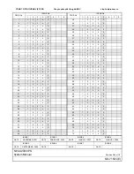
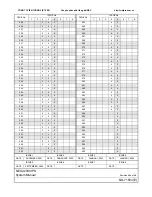
Page 3: ...4 5 22 1 2 3 4 5 23 1 2 3 4 5 24 1 2 3 4 5 25 1 2 3 4 5 26 1 2 3 4 5 27 1 2 3 4 5 28 1 2 3 4 5 29 1 2 3 4 5 30 1 2 3 4 5 31 1 2 3 4 5 32 1 2 3 4 5 33 1 2 3 4 5 34 1 2 3 4 5 35 1 2 3 4 5 36 1 2 3 4 5 37 1 2 3 4 5 38 1 2 3 4 5 39 1 2 3 4 5 40 1 2 3 4 5 41 1 2 3 4 5 42 1 2 3 4 5 43 1 2 3 4 5 44 1 2 3 4 5 45 1 2 3 4 5 46 1 2 3 4 5 47 1 2 3 4 5 48 1 2 3 4 5 49 1 2 3 4 5 50 1 2 3 4 5 51 1 2 3 4 5 52 1 2...

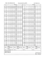
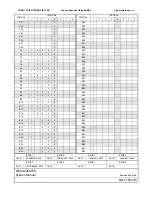
Page 4: ... 98 1 2 3 4 5 99 2 3 4 5 100 2 3 4 5 101 2 3 4 5 102 2 3 4 5 103 2 3 4 5 104 2 3 4 5 105 2 3 4 5 106 2 3 4 5 107 2 3 4 5 108 2 3 4 5 109 2 3 4 5 110 2 3 4 5 PAGE No ISSUE No 1 2 3 4 5 6 7 8 111 2 3 4 5 112 2 3 4 5 113 2 3 4 5 114 2 3 4 5 115 2 3 4 5 116 2 3 4 5 117 2 3 4 5 118 2 3 4 5 119 2 3 4 5 120 2 3 4 5 121 2 3 4 5 122 2 3 4 5 123 2 3 4 5 124 2 3 4 5 125 2 3 4 5 126 2 3 4 5 127 2 3 4 5 128 2 ...

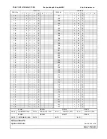
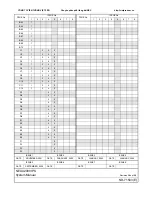
Page 5: ... 4 5 171 2 3 4 5 172 2 3 4 5 173 3 4 5 174 3 4 5 175 3 4 5 176 3 4 5 177 3 4 5 178 3 4 5 179 3 4 5 180 3 4 5 181 3 4 5 182 3 4 5 183 3 4 5 184 3 4 5 185 3 4 5 186 3 4 5 PAGE No ISSUE No 1 2 3 4 5 6 7 8 187 3 4 5 188 3 4 5 189 3 4 5 190 3 4 5 191 3 4 5 192 3 4 5 193 3 4 5 194 3 4 5 195 3 4 5 196 3 4 5 197 3 4 5 198 3 4 5 199 3 4 5 200 3 4 5 201 3 4 5 202 3 4 5 203 3 4 5 204 3 4 5 205 3 4 5 206 3 4 ...

Page 6: ... 3 4 5 244 3 4 5 245 3 4 5 246 3 4 5 247 3 4 5 248 3 4 5 249 3 4 5 250 3 4 5 251 3 4 5 252 3 4 5 253 3 4 5 254 3 4 5 255 3 4 5 256 3 4 5 257 3 4 5 258 3 4 5 259 3 4 5 260 3 4 5 261 4 5 262 4 5 PAGE No ISSUE No 1 2 3 4 5 6 7 8 263 4 5 264 4 5 265 4 5 266 4 5 267 4 5 268 4 5 269 4 5 270 4 5 271 4 5 272 4 5 273 4 5 274 4 5 275 4 5 276 4 5 277 4 5 278 4 5 279 4 5 280 4 5 281 4 5 282 4 5 283 4 5 284 4 ...

Page 7: ... 5 B6 1 2 3 4 5 B7 1 2 3 4 5 B8 1 2 3 4 5 B9 1 2 3 4 5 B10 1 2 3 4 5 B11 1 2 3 4 5 B12 1 2 3 4 5 B13 1 2 3 4 5 B14 1 2 3 4 5 B15 1 3 4 5 B16 1 3 4 5 B17 1 3 4 5 B18 1 3 4 5 B19 1 3 4 5 B20 1 3 4 5 B21 1 3 4 5 B22 1 3 4 5 B23 1 3 4 5 B24 1 3 4 5 PAGE No ISSUE No 1 2 3 4 5 6 7 8 B25 1 B26 1 B27 1 B28 1 B29 1 B30 1 B31 1 B32 1 B33 1 B34 1 B35 1 B36 1 B37 1 B38 1 B39 1 B40 1 B41 1 B42 1 B43 1 B44 1 B4...

Page 8: ...B64 1 B65 1 B66 1 B67 1 B68 1 B69 1 B70 1 C1 1 3 4 5 C2 1 3 4 5 C3 1 3 4 5 C4 1 3 4 5 C5 1 3 4 5 C6 1 3 4 5 C7 1 3 4 5 C8 1 3 4 5 C9 1 3 4 5 C10 1 3 4 5 C11 1 3 4 5 C12 1 3 4 5 D1 4 5 D2 4 5 D3 4 5 D4 4 5 D5 4 5 D6 4 5 D7 4 5 D8 4 5 E1 4 5 E2 4 5 E3 4 5 E4 4 5 E5 4 5 E6 4 5 F1 5 F2 5 F3 5 F4 5 PAGE No ISSUE No 1 2 3 4 5 6 7 8 PAGE No ISSUE No 1 2 3 4 5 6 7 8 CÔNG TY VIỄN THÔNG VIỆT PRO Chuyên phân...

Page 9: ... CONDITIONS 23 Conditions for Overall System 23 Conditions for DtermIP 24 Conditions for Peer to Peer Connection 24 Conditions for Public Network Tie Line Network Connection 24 Common Conditions for CCIS Connection and H 323 Connection 24 Conditions for CCIS Connection 25 Conditions for H 323 Connection 26 Conditions for IP PAD 26 Conditions for DRS 27 Conditions for Legacy Interface LT AP 28 Cond...

Page 10: ...g 4VCT Card 72 Mounting Conditions of IPT 4VCT Card 73 BUS Cable Connection between IPT and 4VCT Cards 75 LAN Cable Connection of IPT Card 76 CHAPTER 3 SYSTEM DATA PROGRAMMING 77 HOW TO READ THIS CHAPTER 78 PRECAUTIONS 79 System Data Backup 79 PROGRAMMING PROCEDURE 80 BASIC DATA SETTING 81 Office Data Conversion 82 System Data Memory All Clear 83 Key FD Data Loading 85 Setting System Clock 86 Sett...

Page 11: ...TUAL IPT DATA ASSIGNMENT 159 Programming Procedure for CCIS Virtual IPT 159 Virtual IPT Data Assignment 160 LOCATION DATA ASSIGNMENT 176 IP FEATURE PROGRAMMING 189 Automatic Program Download for IP Enabled Dterm DtermIP 190 Bandwidth Control 199 Call Forwarding Logout Dterm IP 204 FAX over IP 213 Modem over IP 224 SNMP 231 H 323 IP TRUNK DATA ASSIGNMENT 244 Programming Procedure for H 323 IP Trunk...

Page 12: ...0 B14 APPENDIX C REMOTE PIM OVER IP SAMPLE SETUP C1 SAMPLE SYSTEM CONFIGURATION C2 CONDITIONS FOR SAMPLE SYSTEM C4 LIST OF COMMANDS C5 SETUP THE SYSTEM C11 APPENDIX D VOICE QUALITY MEASURES IN IP PAD D1 COUNTERMEASURES FOR ECHO D2 COUNTERMEASURES FOR OTHERS D8 APPENDIX E TCP UDP RTP PORT NUMBER CONDITIONS E1 TCP UDP RTP PORT NUMBER CONDITIONS E2 APPENDIX F FULL DUPLEX HALF DUPLEX CONDITIONS OF LAN...

Page 13: ...lains the required equipment and hardware installation procedure such as mounting cards and connecting cables for the system CHAPTER 3 SYSTEM DATA PROGRAMMING This chapter explains the programming procedure of the system data Dterm IP setup procedure and Dterm IP login logout procedure CHAPTER 4 CIRCUIT CARD INFORMATION This chapter explains the mounting location the meaning of lamp indications an...

Page 14: ...es how to reduce echoes in 2000 IPS and the setup method APPENDIX E TCP UDP RTP PORT NUMBER CONDITIONS This appendix explains the default TCP UDP RTP port number and range of the available TCP UDP RTP port numbers used in 2000 IPS APPENDIX F FULL DUPLEX HALF DUPLEX CONDITIONS OF LAN INTERFACE This appendix explains the Full Duplex Half Duplex conditions of the LAN Interface cards SEPTEMBER 15 2004...

Page 15: ...Dterm IP usually unless we need to mention the type of ter minal in particular Dterm IP IP Adapter Type For North America Only Dterm IP IP Bundled Type Dterm IP INASET Dterm SP20 Dterm SP30 NOTE 1 Dterm 75 Series E Dterm 85 Series i terminal can be used as the IP terminal by attaching the IP Adapter IP Enabled Dterm This terminal provides users with all features currently avail able in Dterm IP NO...

Page 16: ...ting procedure CCIS System Manual Contains the system description hardware installation procedure programming procedure and oper ation test procedure for the CCIS System ISDN System Manual Contains the system description hardware installation procedure programming procedure and oper ation test procedure for the ISDN System WCS System Manual Contains the system description hardware installation pro...

Page 17: ...ocedure for the NEAXMail AD 8 Voice Mail System SMDR MCI PMS Interface Specifications Contains the interface specifications for Station Message Detail Recording SMDR Message Cen ter Interface MCI Property Management System PMS and PMS operation NEAX IPSDM Hardware Installation Guide Contains the general information and installation procedure for the NEAX IPSDM Internet Protocol Server Distributed ...

Page 18: ... 6 ND 71503 E Rev 5 0 9pch0001 fm THIS PAGE LEFT BLANK INTENTIONALLY JANUARY 31 2003 CÔNG TY VIỄN THÔNG VIỆT PRO Chuyên phân phối tổng đài NEC http vietpro com vn ...

Page 19: ...a tures for the system SYSTEM OUTLINE 8 STATION TO STATION CONNECTION 9 PUBLIC NETWORK TIE LINE NETWORK CONNECTION 10 CCIS CONNECTION 11 H 323 CONNECTION 12 REMOTE PIM OVER IP SYSTEM OUTLINE 13 EQUIPMENT NAME AND FUNCTION 16 SYSTEM CONDITIONS 23 SYSTEM CAPACITY 36 SERVICE FEATURES 44 SEPTEMBER 15 2004 CHAPTER 1 GENERAL INFORMATION CÔNG TY VIỄN THÔNG VIỆT PRO Chuyên phân phối tổng đài NEC http viet...

Page 20: ...cessor cards can be mounted in the system to provide the Legacy PBX features that use the Time Division Switch TDSW The illustration below shows the typical system outline System Outline of 2000 IPS Dterm IP Client PC Dterm IP Router Router MAT via LAN Router H 323 GK LAN Switching HUB Dterm IP Client PC INTERNET INTRANET Switching HUB 100 Mbps DHCP Server PBX 1 board MP C O IP PAD TIE 2000 IPS SL...

Page 21: ...ice data This card is used to control and convert the voice data The MP card manages control signals in both types of connections The illustration below shows a system outline of Station to Station Connection System Outline of Station to Station Connection Dterm IP Legacy Terminal Voice Data Peer to Peer Connection LC DLC TDSW Control Signal Voice Data MP IP PAD Dterm IP Dterm IP LAN PROTIMS over ...

Page 22: ...low shows a system outline of Public Network Tie Line Network Connection System Outline of Public Network Tie Line Network Connection Dterm IP Dterm IP TRUNK IP PAD IP PAD LAN MP MP TDSW TDSW Voice Data Control Signal PSTN GSTN TIE LINE TRUNK LC DLC Legacy Terminal 2000 IPS 2000 IPS 2400 IPX Control Signal LAN Legacy Terminal TRUNK For ISDN PRI PRT For ISDN BRI BRT For GSTN COT For Tie Line Digita...

Page 23: ...he Virtual IPT manages control signals in both types of con nections The illustration below shows a system outline of CCIS Connection System Outline of CCIS Connection NOTE When the destination office uses the physical IPT card for example when connecting to the former PBX system the IPT card and 4VCT card are required in both offices In this case refer to the NEAX 2000 IVS2 NEAX 2000 INTEGRATED V...

Page 24: ...ression the 4VCT card is required For Legacy terminal connection via the IP network with H 323 protocol the IPT card is required For voice compression the 4VCT card is required The illustration below shows a system outline of H 323 Connection System Outline of H 323 Connection 4VCT Dterm IP Dterm IP H 323 IPT IP PAD IP PAD LAN LAN MP MP TDSW TDSW Voice Data Control Signal ROUTER ROUTER INTRANET Ga...

Page 25: ...s a stand alone system IPSDMR IPS Distributed Model Remote with PN CP31 A PN CP31 B IPSDM IPS Distributed Model with PN CP24 A PN CP24 B Following figure shows an image of Remote PIM over IP system System Outline of Remote PIM over IP Outline of System Operation The MP card of Main Site controls call processing and Remote Site follows the Main Site in normal operation mode Remote Site can accommod...

Page 26: ...ccurs Keep Alive signal is not received Remote Site resets the own system and starts survival mode operation as a stand alone system to control the call processing within the Re mote Site During survival mode operation Remote Site system checks regularly whether the communications with Main Site is possible or not When the Remote Site regards that the communications are possi ble the Remote Site w...

Page 27: ...lure Link Down Notice Outline Router PSTN GSTN Main Main Office Administrator Remote Office Administrator 2 Press the button and the message is display on LCD Link Down to Site xx Notice button is flashing 1 Remote Router 2 Press the button and the message is display on LCD Link Down to Site xx Notice button is flashing 1 IP Network DOWN JANUARY 31 2003 REMOTE PIM OVER IP SYSTEM OUTLINE CÔNG TY VI...

Page 28: ...663 PIMMG For PBC PIM Port Interface Module PIM Maximum 64 physical ports per PIM Houses two batteries for protection from short power interruption for 30 minutes At maximum configuration the system consists of eight PIMs and provides a total of 512 physical ports 64 ports 8 SN1658 PIMMF PIM Port Interface Module PIM for Backup CPU System Maximum 64 physical ports per PIM Houses two batteries for ...

Page 29: ...p cover assembly is required for each stack TOP COVER ASSEM SN1619 BATTMB BATTM Battery Module for housing PIM or CS ZT backup batteries Houses two pairs of batteries for protection from long power inter ruption for 3 hours SN1671 BATTMG For PBC BATTM Battery Module for housing PIM backup batteries Houses two pairs of batteries for protection from long power inter ruption for 3 hours JANUARY 31 20...

Page 30: ...egistra tion Server DRS built in FP Virtual FP built in OAI built in SMDR on RS 232C built in SMDR on IP built in PMS on IP Virtual IPT Virtual CSH 33 MHz PCI BUS Memory SDRAM 32MB Flash ROM 9MB TDSW 1024CH 1024CH 16 line CFT PB sender Clock 2 line PLO receiver mode source mode two RS 232C ports 2 line DAT Recording duration Maximum 128 seconds DK 4 line PB receiver Modem for remote mainte nance 3...

Page 31: ... mainte nance 33 6 Kbps internal Music on Hold tone BUS interface BUS interface functions as a driver receiver of various signals adjusts gate delay timing and cable delay timing monitors I O Bus and PCM BUS Two cards are required per Backup CPU system One card for active MP MP0 and another card for stand by MP MP1 Series 3400 software enhancement PZ M606 A ETHER Ethernet Control Card Mounted on M...

Page 32: ...t to ON OFF by the switch setting Used together with maximum two 16VCT cards Two cards can be accommodated per built in FP FP card maxi mum 8 per system 10BASE T 100BASE TX twisted pair cable is connected directly to this card PN 16VCTA PN 16VCTA A 16VCT 16 channel CODEC Card for 32 channel IP PAD Card Provides voice compression DSP control functions such as voice compression control DTMF relay an...

Page 33: ...bps G 723 1 5 3 Kbps 6 3 Kbps G 729a 8 Kbps NOTE FAX protocol Pass through G 711 G 726 Provides Auto Negotiation function Always set to ON When using SPN 8IPLA IP PAD A Set to ON OFF by the switch setting When using SPN 8IPLA IP PAD B When mounting 24DSP PZ 24IPLA card this card can provides up to 32 channel of IP PAD When using G 723 1 provides up to 24 channel of IP PAD Two cards can be accommod...

Page 34: ...receiving compressed voice or signals over IP network Provides Auto Negotiation function Set to ON OFF by the switch setting Used together with maximum of three 4VCT PN 4VCTI cards 12 channels 10BASE T 100BASE TX twisted pair cable is connected directly to this card PN 4VCTI 4VCT 4 channel CODEC Card for IP Trunk Card Provides voice compression DSP control functions such as voice compression contr...

Page 35: ...ect the Line Trunk cards The DTMF sender signal width of Dterm Dterm IP is 112 128 ms When upgrading the software of the system from Series 3200 R6 2 or before to Series 3300 or later the office data conversion is required For details see Page 82 When connecting the MP card IP PAD card IP terminal and the switching HUB which Spanning Tree IEEE 802 1d is available communication failures shown below...

Page 36: ...voice compression in the system Conditions for Public Network Tie Line Network Connection For the Dterm IP communication between offices the IP PAD card is required Peer to Peer connection is not available in this connection Common Conditions for CCIS Connection and H 323 Connection The service features requiring continuous voice transmission such as Background Music should not be used because the...

Page 37: ...isplayed regardless of idle or busy state of Dterm Dterm IP writing the message over the present display After six seconds the display returns to the time display automatically The system detects a Link Down on the condition that TCP connection between offices is interrupted The Link Down is notified to the Dterm Dterm IP at 15 20 seconds later from the system detects the Link Down Link Down Notic...

Page 38: ...d number depends on the mounting location on the PIM The IP PAD card uses 32 channels ports even if mounting one or no 16VCT card per IP PAD card Do not pull out the 16VCT card from the PIM or IPTRK BUS CA cable from the IP PAD 16VCT card while the MP card is On line mode If the 16VCT card or IPTRK BUS CA is pulled out in On line mode the IP PAD card operates ab normally When mounting no 16VCT car...

Page 39: ... through IP PAD card SPN 8IPLA IP PAD A SPN 8IPLA IP PAD B is mounted G 726 pass through IP PAD card SPN 8IPLA IP PAD B is mounted Series 3400 software required PN 32IPLA IP PAD card does not support FAX communication When providing the FAX communication T 30 with the PN 32IPLA A card following condition is required 16VCT card SPN 16VCTAA IP PAD A SPN 16VCTAA IP PAD B is mounted Series 3200 R6 2 s...

Page 40: ...AN Conditions for Remote PIM over IP System Series 3200 R6 2 software required General Conditions We recommend that you should install the same version of software in the MP cards of Main Site and Remote Sites The way of loading and conditions of Key FD are following The same number of Key FD for remote site licence as the number of remote sites are required for Remote PIM over IP system The requi...

Page 41: ...ranteed network is preferable such as IP VPN Layer 3 VPN or wide area Ethernet service Lay er 2 VPN The following table shows the permissible delay time in the network If the network is short of the requirement it may cause the delay operation of system the delay and deterioration of voice packets disconnection of calls and frequent changeover to survival mode at Remote Site The MP card of Remote ...

Page 42: ...th America the CSH and CSI cards for wireless system cannot be used at Remote Site according to UTAM regulation LT IP PAD 32IPLA A 8IPLA 16VCTA A or 16VCTA DLC NOTE LC COT LDT ODT CSI NOTE Attendant Console Desk Console Add On Module DSS BLF Console are not mount able at Remote Site Remote Site cannot accommodate the following FP AP LT cards FP FP card CP15 CP19 is not mountable at Remote Site AP ...

Page 43: ...redetermined time set by CM0B Y 31 60 50 on normal mode operation b When Remote Site cannot be connected to Main Site or is not allowed to connect to Main Site after the system reset of the Remote Site Remote Site is reset automatically to change the operation from normal mode to survival mode when it detects an interruption of the communications from to Main Site When Remote Site starts the survi...

Page 44: ...e Site are as follows Attendant Console Desk Console Add On Module DSS Console and ISDN Terminal are not mountable Caller ID Station is not available CCIS CCH with digital and analog trunk interface is not available CCIS CCT is available All services using MP built in DK or DK card are not available All services using DAT card are not available When Remote Site is IPSDMR in addition to the above c...

Page 45: ... Remote Site The MJ MN alarm indications are not available at Remote Site If a fault occurs at Remote Site the fault is notified to the Main Site and MJ MN alarm is indicated at the Main Site On line expansion for LC DLC COT cards is supported and it enables the tone path connection even if the system data copy is not activated to the Remote Site After completing all expansions for LC DLC COT card...

Page 46: ...ter from the system detects the Link Down When the link between Main Site and Remote Site is interrupted the lamp of Dterm DtermIP button becomes the state as shown below Then press the button the LCD of the Dterm Dterm IP displays the following COLOR AND STATE OF BUTTON STATE AND OPERATION LCD DISPLAY Red Flashing Momentarily 0 125 seconds ON 0 125 seconds OFF Link Down occurrence Red Flashing Sl...

Page 47: ...m DtermIP button keeps flashing during the Remote Site op erates on survival mode Since the color of lamp and the indication interval changes an administrator at the Remote Office can changeover the system operation from survival mode to normal remote mode according to this indication When the link between Main Site and Remote Site recovers and the Remote Site starts subordinate operation to the M...

Page 48: ...8 PIM Physical PIM 8 2 Site 2 Site 31 Virtual PIM 7 2 Site 2 Site FP Built in FP on MP 1 8 1 Site 8 Site 1 Site 8 Site 60 64 FP card PN CP15 PN CP19 3 N A N A Virtual FP for Dterm IP 7 2 Site 2 Site Virtual FP for PS 4 N A N A 4 AP IPT Card 8 8 24 N A N A 24 Virtual IPT NOTE 1 1 N A N A CCH Card 8 N A N A CCT Card 8 6 Site 6 Site 6 Site 6 Site CSH Card NOTE 2 24 3 Site 3 Site Other Major AP Card D...

Page 49: ...12 96 Site 80 Site 512 Physical PIM Port for CCIS IPT Point to Point Connection NOTE 4 136 N A N A 136 Physical PIM Port for CCIS IPT Point to MultiPoint Con nection NOTE 4 135 NOTE 7 N A N A 135 Physical PIM Port for H 323 IPT NOTE 4 96 N A N A 96 IP Port Virtual PIM Port for Dterm IP 448 448 128 Site 128 Site 448 784 Virtual PIM Port for IP CS NOTE 5 448 64 Site 64 Site 448 PS Port Virtual PIM P...

Page 50: ...Site 448 PS 256 80 Site 80 Site 256 DSS Console 32 N A N A 32 DESKCON 8 N A N A 8 CS ZT 128 128 24 Site 20 Site 128 128 IP CS 112 64 Site 16 Site 112 LAN Inter face When using IP PAD card 8 2 2 32 When using Virtual IPT IPT card 8 Number of Virtual PIM for Virtual IPT NOTE 10 2 2 Number of Channel for Virtual IPT NOTE 10 127 127 Number of Destination IP Address NOTE 10 255 255 Number of VCT Channe...

Page 51: ...e total number of the following ports is maximum 256 per Remote Site Physical PIM Port Line Trunk IP PAD CS ZT Virtual PIM Port Dterm IP IP CS Physical PIM Port AP card NOTE 7 The total number of B channel of the following trunk is maximum 127 CCIS Virtual IPT CCIS IPT Port Point to Multipoint connection NOTE 8 Since maximum of 64 FP AP in whole system are divided into Remote Sites and one Remote ...

Page 52: ... A Virtual FP for DtermIP 15 2 Site 2 Site Virtual FP for PS 4 N A N A 4 AP IPT Card 8 8 24 N A N A 24 Virtual IPT NOTE 1 1 N A N A CCH Card 8 N A N A CCT Card 8 6 Site 6 Site 6 Site 6 Site CSH Card NOTE 2 24 3 Site 3 Site Other Major AP Card DTI T1 E1 8 6 Site 6 Site PRT 8 6 Site 6 Site BRT 24 6 Site 6 Site Virtual CSH NOTE 2 8 8 Site 1 Site 24 ETH ER ETHER Card NOTE 3 1 2 1 2 Site 1 Site 64 IP P...

Page 53: ...ort for CCIS IPT Point to Point Connection NOTE 4 136 N A N A 136 Physical PIM Port for CCIS IPT Point to MultiPoint Con nection NOTE 4 135 NOTE 7 N A N A 135 Physical PIM Port for H 323 IPT NOTE 4 96 N A N A 96 IP Port Virtual PIM Port for Dterm IP 956 956 128 Site 128 Site 956 Virtual PIM Port for IP CS NOTE 5 512 64 Site 64 Site Virtual PIM Port for CCIS Virtual IPT NOTE4 128 NOTE 7 N A N A PS ...

Page 54: ...2 DtermIP 956 128 Site 128 Site 956 DSS Console 32 N A N A 32 DESKCON 8 N A N A 8 CS ZT 128 128 24 Site 20 Site 128 128 IP CS 128 64 Site 16 Site 128 LAN Inter face When using IP PAD card 8 2 2 32 When using Virtual IPT IPT card 8 Number of Virtual PIM for Virtual IPT NOTE 12 2 2 Number of Channel for Virtual IPT NOTE 12 127 127 Number of Destination IP Address NOTE 12 255 255 Number of VCT Channe...

Page 55: ...CS ZT Virtual PIM Port Dterm IP IP CS Physical PIM Port AP card NOTE 7 The total number of B channel of the following trunk is maximum 127 CCIS Virtual IPT CCIS IPT Port Point to Multipoint connection NOTE 8 The number of virtual lines assigned on Dterm 1020 number of Dterm Dterm IP NOTE 9 The number of visitor PS for wireless roaming is included The number of Visitor Location Register is maximum ...

Page 56: ...rica Call Forwarding set by DISA with AP01 NOTE Add On Module For North America Add On Module Dterm For other than North America is not available for Dterm IP OAI Built in OAI is available on the MP card excluding the following interface and facility NOTE The port number of 2000 IPS for OAI is 60030 in initial The port number 1024 1025 1039 are available by CM0B Y 00 98 Maximum four applications c...

Page 57: ...l Forwarding Call Transfer All Calls Hotline Do not Disturb Dterm Calling Called Number Display Digital Display Trunk Speed Calling System Speed Calling Station Bearer Service Tandem Switching of TIE Trunks 2 4 Wire The Line Connection with PAD Control Outgoing Trunk Busy Announcement Brokerage Hot Line Outside Least Cost Routing 3 6 Digit LCR Time of Day Routing Attendant Manual Override Echo Can...

Page 58: ... 46 ND 71503 E Rev 5 0 9pch1001 fm THIS PAGE LEFT BLANK INTENTIONALLY SEPTEMBER 15 2004 CÔNG TY VIỄN THÔNG VIỆT PRO Chuyên phân phối tổng đài NEC http vietpro com vn ...

Page 59: ...re installation pro cedure such as mounting cards and connecting cables for the system PRECAUTIONS 48 REQUIRED EQUIPMENT 55 INSTALLATION PROCEDURE 59 INSTALLATION PROCEDURE FOR H 323 CONNECTION 71 SEPTEMBER 15 2004 CHAPTER 2 INSTALLATION CÔNG TY VIỄN THÔNG VIỆT PRO Chuyên phân phối tổng đài NEC http vietpro com vn ...

Page 60: ...t of the circuit that supplies the PBX Bare covered or insulated grounding conductors are acceptable Individually covered or insulated equipment grounding conductors shall have a continuous outer finish that is either green or green with one or more yellow stripes The equipment grounding connector is to be connected to ground at the service equipment The attachment plug receptacles near the PBX ar...

Page 61: ...rds from static electricity Static Electricity Guard WHEN PLUGGING UNPLUGGING A CIRCUIT CARD WHEN HOLDING A CIRCUIT CARD Continued on next page FRAME GROUND SCREW PBX WRIST STRAP NEVER TOUCH THE COMPONENTS OR SOLDERED SURFACE WITH BARE HANDS CARD FRONT PRECAUTIONS CÔNG TY VIỄN THÔNG VIỆT PRO Chuyên phân phối tổng đài NEC http vietpro com vn ...

Page 62: ...aging in such work the installer must be careful not to cause damage by static electricity WEAR A WRIST STRAP AND PERFORM THE WORK ON A GROUNDED CONDUCTIVE WORK SURFACE CIRCUIT CARD WHEN CARRYING A CIRCUIT CARD AROUND KEEP THE CARD IN A CONDUCTIVE POLYETHYLENE BAG CIRCUIT CARD CONDUCTIVE POLYETHYLENE BAG ATTENTION Contents Static Sensitive Handling Precautions Required PRECAUTIONS CÔNG TY VIỄN THÔ...

Page 63: ... card controlling the IP PAD 4VCT cards Inserting or extracting the 16VCT 4VCT cards during data transmission Plugging or unplugging the BUS cable IPT TRK BUS CA between the IP PAD and 16VCT IPT and 4VCT cards After the above operations turn OFF the MB switch Be sure to insert all of the 16VCT 4VCT cards firmly into their slots which are connected to the IP PAD IPT card by the BUS cable Otherwise ...

Page 64: ...rea you may be exposed to hazard voltages 2 You must wait for 30 seconds before plugging the circuit card again when unplugging the circuit card while the operating power is being supplied CARD FRONT NEVER TOUCH THE COMPO NENTS OR SOLDERED SUR FACE WITH BARE HANDS PBX SEPTEMBER 15 2004 PRECAUTIONS CÔNG TY VIỄN THÔNG VIỆT PRO Chuyên phân phối tổng đài NEC http vietpro com vn ...

Page 65: ...hen the operating power is being supplied to the PZ PW121 PZ PW126 card do not plug unplug this circuit card into from its mounting slot 2 When the system is configured with two or more PIMs the BUS cable is providing gang con trol for the PZ PW121 PZ PW126 card of PIM0 and other PIMs Therefore if the power of PIM0 is off no power is supplied to the whole system even when the power switches of oth...

Page 66: ...g power off inspect all line trunk cards busy lamps to verify that no cards are operating 2 Turn the SW1 switches of all the PZ PW121 PZ PW126 cards to OFF First turn OFF PIM0 Then turn OFF PIM1 to PIM7 PRECAUTIONS CÔNG TY VIỄN THÔNG VIỆT PRO Chuyên phân phối tổng đài NEC http vietpro com vn ...

Page 67: ...e card per MP 2 Mount on PN CP27 A card One card per MP 10BASE T Cable TIA EIA category 3 or larger 100BASE TX Cable TIA EIA category 5 10BASE T 100BASE TX Cable between Ether Card and Ethernet IP PAD Card and Ethernet IPT Card and Ethernet As required Cable length Maximum 100m 328 ft For IP PAD 100BASE TX is recommended Router NOTE CiscoRouteris recommended As required HUB NOTE Switching HUB is r...

Page 68: ...8 sets PN 8IPLA IP PAD 8 channel IP PAD Card 1 8 PZ 24IPLA 24DSP 24 channel DSP Card for 8 channel IP PAD Card 1 8 LT Card Line Trunk Card for Leg acy Terminal Interface As required 128 ports per FP 512 ports per system AP Card Application Processor Card As required 256 ports per system PN CP15 PN CP19 FP FP Card 1 3 For maximum 128 Legacy terminals FP card is not required For more than 128 Legacy...

Page 69: ...to Legacy ter minal Dterm DtermIP con nection via CCIS IP PAD card is required PN 16VCTA PN 16VCTA A 16VCT 16 channel CODEC Card 1 16 IPTRK BUS CA Set of 3 BUS Cables between IP PAD and 16VCT Cards 1 8 sets PN 8IPLA IP PAD 8 channel IP PAD Card 1 8 PZ 24IPLA 24DSP 24 channel DSP Card for 8 channel IP PAD Card 1 8 JANUARY 16 2004 REQUIRED EQUIPMENT CÔNG TY VIỄN THÔNG VIỆT PRO Chuyên phân phối tổng ...

Page 70: ...16 IPTRK BUS CA Set of 3 BUS Cables between IP PAD and 16VCT Cards 1 8 sets PN 8IPLA IP PAD 8 channel IP PAD Card 1 8 PZ 24IPLA 24DSP 24 channel DSP Card for 8 channel IP PAD Card 1 8 PN IPTB IPT IP Trunk Card 1 8 For H 323 connection IPT card and 4VCT card are required PN 4VCTI 4VCT 4 channel CODEC Card 1 32 IPTRK BUS CA Set of 3 BUS Cables between IPT and 4VCT Cards 1 8 sets Gatekeeper Gatekeepe...

Page 71: ...TART Page 61 Mounting ETHER Card MP Card Page 62 Mounting IP PAD Card Page 67 Mounting 16VCT Card Page 68 BUS Cable Connection Page 69 LAN Cable Connection of between IP PAD and 16VCT Cards IP PAD Card Page 70 LAN Cable Connection of ETHER Card H 323 connection is To Installation Procedure for H 323 Connection on next page No required Yes JANUARY 16 2004 INSTALLATION PROCEDURE CÔNG TY VIỄN THÔNG V...

Page 72: ...onditions of IPT 4VCT Card Page 73 END START Page 71 NOTE Mounting IPT Card Page 72 NOTE Mounting 4VCT Card Page 75 BUS Cable Connection between IPT and 4VCT Cards Page 76 LAN Cable Connection of IPT Card FEBRUARY 28 2002 INSTALLATION PROCEDURE CÔNG TY VIỄN THÔNG VIỆT PRO Chuyên phân phối tổng đài NEC http vietpro com vn ...

Page 73: ...27 A card to the appropriate position See CHAPTER 4 Page 278 Page 283 2 To provide LAN interface mount the ETHER card on the MP card See CHAPTER 4 Page 288 3 Mount the MP card in the MP slot of PIM0 ATTENTION Contents Static Sensitive Handling Precautions Required JANUARY 31 2003 INSTALLATION PROCEDURE CÔNG TY VIỄN THÔNG VIỆT PRO Chuyên phân phối tổng đài NEC http vietpro com vn ...

Page 74: ... PIM7 For the retrofit system see Page 65 Maximum of two IP PAD cards per built in FP on MP card FP card maximum of eight per system can be mounted For PN 32IPLA PN 32IPLA A LT01 in PIM0 2 4 6 IP PAD No 0 LT05 in PIM0 2 4 6 IP PAD No 1 LT01 in PIM1 3 5 7 IP PAD No 2 LT05 in PIM1 3 5 7 IP PAD No 3 For PN 8IPLA LT00 in PIM0 2 4 6 IP PAD No 0 LT04 in PIM0 2 4 6 IP PAD No 1 LT00 in PIM1 3 5 7 IP PAD N...

Page 75: ...ystem LT08 LT10 slots when you mount the IP PAD PN 32IPLA PN 32IPLA A card in LT05 slot AP cards are mountable in AP08 AP11 slots for Backup CPU system AP08 AP10 slots Continued on next page VM LT00 LT01 LT02 LT03 LT04 LT05 LT06 LT07 LT08 LT09 LT10 LT11 MP12 FP12 PFT IP PAD IP PAD PIM0 2 4 6 L T must not be mounted IP PAD No 0 IP PAD No 1 must be vacant except the 16VCT card VM LT00 LT01 LT02 LT03...

Page 76: ...equired slots LT00 LT04 and two adjoining slots LT01 LT02 LT05 LT06 Only AP cards are mountable in LT01 LT02 LT05 LT06 When using IP PAD PN 8IPLA card with 32 channel Required slots LT00 LT04 and three adjoining slots LT01 LT02 LT03 LT05 LT06 LT07 Only AP cards are mountable in LT01 LT02 LT03 LT05 LT06 LT07 NOTE 4 When using Series 3200 R6 2 software or before in the system mount the IP PAD PN 8IP...

Page 77: ...LT04 in PIM0 IP PAD No 0 LT01 LT04 in PIM1 IP PAD No 2 NOTE The using number of channels in the IP PAD card depends on the office data CM0A Y 73 Also the required slot for the IP PAD card depends on the using number of channel in the IP PAD card For details see Mounting IP PAD Card 3 Page 62 Illustrations shown above are explaining the case of using 32 channels in the IP PAD card PIM0 LT00 LT01 LT...

Page 78: ...0 LT04 LT07 in PIM0 IP PAD No 1 NOTE The using number of channels in the IP PAD card depends on the office data CM0A Y 73 Also the required slot for the IP PAD card depends on the using number of channel in the IP PAD card For details see Mounting IP PAD Card 3 Page 62 Illustrations shown above are explaining the case of using 32 channels in the IP PAD card must be vacant except the IP PAD card PI...

Page 79: ...en IP PAD card is mounted in LT01 slot Mount VCT1 in LT03 When IP PAD card is mounted in LT05 slot Mount VCT1 in LT07 16VCT Mounting Slot NOTE Do not mount any other L T cards in LT08 LT11 slots for Backup CPU system LT08 LT10 slots when you mount the 16VCT card in LT06 and LT07 slots AP cards are mountable in AP08 AP11 slots for Backup CPU system AP08 AP10 slots ATTENTION Contents Static Sensitiv...

Page 80: ...nnection NOTE The IPTRK BUS CA consists of a set of three identical cables Make sure to connect the IP PAD and 16VCT cards by using this set of cables confirming that connecting location of each cable must be matched in both IP PAD and 16VCT cards as shown in the above figure 16VCT VCT0 VCT1B VCT0B VCT1A VCT0A IP PAD VCTB VCTA LAN 16VCT VCT1 VCT1B VCT0B VCT1A VCT0A IPTRK BUS CA 0 1 m 0 33 ft To Dt...

Page 81: ...d and the Switching HUB by using a 100BASE TX cable IP PAD Switching HUB Cable Connection IP PAD LAN Switching HUB Not used Not used RD Not used Not used RD TD TD 8 7 6 5 4 3 2 1 100BASE TX Cable Maximum 100 m 328 ft Pins RJ 45 Connector INSTALLATION PROCEDURE CÔNG TY VIỄN THÔNG VIỆT PRO Chuyên phân phối tổng đài NEC http vietpro com vn ...

Page 82: ...nection NOTE The port number of 2000 IPS for OAI is 60030 in initial The port number 1024 1025 1039 are available by CM0B Y 00 98 The port number of 2000 IPS for MAT is fixed to 60000 The port number of 2000 IPS for SMDR is fixed to 60010 The port number of 2000 IPS for PMS is fixed to 60050 ETHER LAN Router Switching HUB Not used Not used RD Not used Not used RD TD TD 8 7 6 5 4 3 2 1 10BASE T 100...

Page 83: ...d is mountable per PIM PIM0 7 AP00 11 slots PIM0 for Backup CPU AP00 AP10 slots 3 After mounting the card set the MB switch to DOWN position to put the card in service IPT Mounting Slot ATTENTION Contents Static Sensitive Handling Precautions Required VM AP00 AP01 AP02 AP03 AP04 AP05 AP06 AP07 AP08 AP09 AP10 AP11 MP12 FP12 PFT PIM0 7 IPT card mountable slots Only one IPT card is mountable per PIM ...

Page 84: ... the second to fourth 4VCT VCT1 3 cards into the LT slots next to the 4VCT card mounted above Maximum of four 4VCT cards are mountable per PIM NOTE See Mounting Conditions of IPT 4VCT Card on next page 4VCT Mounting Slot ATTENTION Contents Static Sensitive Handling Precautions Required VM LT00 LT01 LT02 LT03 LT04 LT05 LT06 LT07 LT08 LT09 LT10 LT11 MP12 FP12 PFT PIM0 7 4VCT card mountable slots Max...

Page 85: ...ge NOTE 1 The number in the parentheses shows the available slots in Backup CPU system PIM No OF CHANNEL No OF CARD REQUIRED SLOTS AVAILABLE SLOTS FOR OTHER LT AP CARDS IPT 4VCT PIM0 4 1 1 IPT 1 4VCT 1 Vacant 2 8 7 8 1 2 IPT 1 4VCT 2 Vacant 3 6 5 12 1 3 IPT 1 4VCT 3 Vacant 4 4 3 16 1 4 IPT 1 4VCT 4 Vacant 5 2 1 PIM1 7 4 1 1 IPT 1 4VCT 1 Vacant 0 10 8 1 2 IPT 1 4VCT 2 Vacant 1 8 12 1 3 IPT 1 4VCT 3...

Page 86: ...the LT08 LT11 slots for Backup CPU system LT08 LT10 slots of the same PIM NOTE 3 When the IP PAD card is mounted in the LT05 slot a 4VCT card cannot be mounted in the LT08 LT11 slots for Backup CPU system LT08 LT10 slots of the same PIM JANUARY 31 2003 INSTALLATION PROCEDURE FOR H 323 CONNECTION CÔNG TY VIỄN THÔNG VIỆT PRO Chuyên phân phối tổng đài NEC http vietpro com vn ...

Page 87: ...nnect the IPT and 4VCT cards by using this set of cables confirming that connecting location of each cable must be matched in both IPT and 4VCT cards as shown in the above figure IPT VCTA VCT 4VCT VCT0 IPTA IPT EXPA EXP 4VCT VCT1 IPTA IPT EXPA EXP 4VCT VCT2 IPTA IPT EXPA EXP 4VCT VCT3 IPTA IPT EXPA EXP 4VCT IPTA IPT EXPA EXP IP CONN IPT NOTE VCTA VCT IPCONN To ROUTER HUB IPTRK BUS CA 0 1 m 0 33 ft...

Page 88: ...g a 10BASE T 100BASE TX cable IPT HUB Router Cable Connection IPT HUB Router IPCONN LAN VCT 10BASE T 100BASE TX Cable Maximum 100 m 328 ft Not used Not used RD Not used Not used RD TD TD 8 7 6 5 4 3 2 1 Pins RJ 45 Connector FEBRUARY 28 2002 INSTALLATION PROCEDURE FOR H 323 CONNECTION CÔNG TY VIỄN THÔNG VIỆT PRO Chuyên phân phối tổng đài NEC http vietpro com vn ...

Page 89: ...1 REMOTE PIM OVER IP DATA ASSIGNMENT 96 SYSTEM CONSTITUTION DATA ASSIGNMENT 120 Dterm IP DATA ASSIGNMENT 127 DtermIP SETUP 136 DtermIP LOGIN LOGOUT OPERATION 142 IP PAD DATA ASSIGNMENT 146 CCIS VIRTUAL IPT DATA ASSIGNMENT 159 LOCATION DATA ASSIGNMENT 176 IP FEATURE PROGRAMMING 189 H 323 IP TRUNK DATA ASSIGNMENT 244 SYSTEM DATA BACKUP 266 SYSTEM RESET 268 SEPTEMBER 15 2004 CHAPTER 3 SYSTEM DATA PRO...

Page 90: ...setting Press SW1 switch on the MP card A reset of the IP PAD card is required after data setting Set the Make Busy switch to UP and then DOWN A reset of the IPT card is required after data setting Set the Make Busy switch to UP and then DOWN Command with this marking can be used only under Off Line mode of the MP card To set Off Line mode 1 Set SW3 on the MP card to 2 or 3 2 Press SW1 on the MP c...

Page 91: ...perations Turning Off the system System Initial reset of MP card Changing the MP card to Off Line Mode Changing the MP card to On Line Mode after system data setting under Off Line Mode You can execute the system data backup by the following two ways Executing the system data backup once a day at the time set by CM43 Y 5 00 If no data is set the default setting is 3 00 a m Executing the system dat...

Page 92: ...E 2 Page 268 NOTE 1 Location Data Assignment IP PAD Data Assignment CCIS Virtual IPT Data Assignment H 323 Connection Page 244 H 323 IP Trunk Data Assignment IP Feature Programming Page 189 NOTE 1 Page 146 NOTE 1 System Constitution Data Assignment Page 120 NOTE 1 Remote PIM over IP provide Remote PIM over IP Data Assignment No Yes Page 96 BASIC DATA SETTING Office Data Conversion System Data Memo...

Page 93: ...amming Manual or each System Manual BASIC DATA SETTING For initial system setup you must execute the following Office Data Conversion Page 82 System Data Memory All Clear Page 83 Key FD Data Loading Page 85 Setting System Clock Page 86 Setting Nation Code Page 87 Setting A law µ law Page 88 Setting DTG Music on Hold Tone Page 89 LAN Data Assignment Page 93 VLAN Data Assignment Page 94 JANUARY 16 2...

Page 94: ...ding the software in Retrofit system to Series 3400 or later convert the office data using Office Data Converter in the MATWorX CD ROM then execute the office data conver sion by CM00 90 DESCRIPTION DATA Execute the office data conversion Series 3200 R6 2 software required 1 2 90 0 Start conversion 1 Always displayed after first data 90 is typed NOTE 1 NOTE 1 When first data 90 is typed second dat...

Page 95: ... PIMs CM00 11 1 PIM 7 Virtual PIMs CM00 12 2 PIMs 6 Virtual PIMs CM00 13 3 PIMs 5 Virtual PIMs CM00 14 4 PIMs 4 Virtual PIMs CM05 Y 0 Setting of FP AP Card Type FP AP No Card Type NONE No data 00 00 FP 00 FP 00 FP 00 FP 00 FP 01 00 FP 00 FP 00 FP 00 FP 00 FP 02 00 FP 00 FP 00 FP 00 FP 00 FP 03 00 FP 00 FP 00 FP 00 FP 00 FP 16 NONE 00 FP NONE NONE NONE 17 NONE 00 FP 00 FP 00 FP NONE 18 NONE 00 FP 0...

Page 96: ...05 PIM5 05 PIM5 05 PIM5 19 NONE 07 PIM7 07 PIM7 07 PIM7 07 PIM7 04 15 20 63 NONE NONE NONE NONE NONE CM05 Y 6 Type of FP AP NOTE 1 NOTE 2 FP AP No Type of FP AP NONE No data 00 2 Built in FP 2 Built in FP 2 Built in FP 2 Built in FP 2 Built in FP 01 NONE 0 Virtual FP 0 Virtual FP 3 PN CP15 3 PN CP15 02 NONE 0 Virtual FP 0 Virtual FP 0 Virtual FP 0 Virtual FP 03 NONE 0 Virtual FP 0 Virtual FP 0 Vir...

Page 97: ... for details For other than North America DESCRIPTION DATA B CM00 Clear Command CM05 CM00 1 8 PIMs CM00 11 1 PIM 7 Virtual PIMs CM00 12 2 PIMs 6 Virtual PIMs CM00 13 3 PIMs 5 Virtual PIMs CM00 14 4 PIMs 4 Virtual PIMs CM05 Y 8 Site No PIM No con trolled by each FP PIM No accom modates Virtual IPT FP AP No PIM No Virtual PIM No NONE See NOTE 3 00 NONE 0000 PIM0 NONE NONE NONE 01 NONE 0002 PIM2 0002...

Page 98: ...lock data 1 2 0 Calendar Year 2000 2099 Ex 2002 1 2 1 Date MM DD WW MM 01 12 Month DD 01 31 Date WW 00 Sun 01 Mon 02 Tue 03 Wed 04 Thu 05 Fri 06 Sat 1 2 2 Time HH MM SS HH 00 23 Hour MM 00 59 Minute SS 00 59 Second START CM02 END BASIC DATA SETTING CÔNG TY VIỄN THÔNG VIỆT PRO Chuyên phân phối tổng đài NEC http vietpro com vn ...

Page 99: ...st Russia 04 NOTE 2 In case of PBC the initial data of CM31 Y 0 0 is same as North America nation code 03 Therefore you must set the nation code to 04 by this command DESCRIPTION DATA Specify the nation code 1 2 Y 0 0 01 Australia 02 UK 03 North America 04 Asia Africa Europe Latin America Middle East Russia PBC NOTE 2 15 New Zealand START CM31 INITIAL END JANUARY 31 2003 BASIC DATA SETTING CÔNG TY...

Page 100: ...g PN CP31 A PN CP31 B the system is set to µ law auto matically Set the 2nd data to 0 for A law NOTE 3 Set the same value as remote site CM04 Y 11 40 You cannot set both of A law and µ law in the same Remote PIM over IP system 1 2 Y 10 00 0 A law 1 µ law 2 Not used 3 Depends on the SW2 1 on PN CP24 A PN CP24 B PN CP27 A or the Key ROM SP 3722 IPS KYUS PROG A1 on PN CP31 A PN CP31 B START CM04 END ...

Page 101: ...rogram is for North America or Australia DTG is set to the country automatically This data setting is not required for the combination of the DTG program and the countries marked with asterisk in the table on next page DESCRIPTION DATA Set the DTG Digital Tone Generator for your country Not used in Australia North America UK 1 2 Y 3 00 00 07 See the table on next page START CM48 A JANUARY 16 2004 ...

Page 102: ...Europe A law Standard New Zealand Austra lia UK SP 3645 IPS DTG C1 Asia Hong Kong Taiwan China Thailand Malaysia Sin gapore A law Standard North America SP 3758 IPS DTG D1 PBC Series 3200 R6 2 software required Nether lands Germany Italy Austria Belgium Spain Sweden UK SP 3774 IPS DTG E1 PBC Series 3200 R6 2 software required Denmark Greece Switzer land South Africa B JANUARY 16 2004 BASIC DATA SE...

Page 103: ... 02 North America 03 Australia 04 A law countries 05 Hong Kong 06 Malaysia 07 Singapore 08 UK 09 Mexico 10 Taiwan 11 New Zealand 13 China 14 Thailand 15 Brazil 16 Netherlands 17 Germany 18 Italy 19 Austria 20 Belgium 21 Spain 22 Sweden 23 UK 24 Denmark 25 Greece 26 Switzerland 27 South Africa NONE Not used B CM04 END JANUARY 16 2004 BASIC DATA SETTING CÔNG TY VIỄN THÔNG VIỆT PRO Chuyên phân phối t...

Page 104: ...ata below DESCRIPTION DATA Set the music for Internal Hold Tone NOTE Set CM48 Y 0 00 01 02 1400 af ter this data setting 1 2 Y 3 01 00 Nocturne 01 Minuet 02 Fur Elise 03 The Maiden s Player 04 When the saints go marching in 05 It s a small world 06 Spring by four seasons 07 Let it be 08 Ich bin ein Musikante German folk song 09 If you love me 10 Amaryllis French folk song DESCRIPTION DATA Specify ...

Page 105: ...0000000000 255255255255 IP Address for the system NONE No data Assign the Subnet Mask for the system 1 2 Y 00 01 000000000000 255255255255 Subnet Mask for the system NONE No data Assign the Default Gateway Address for the system 1 2 Y 00 02 000000000000 255255255255 Default Gateway Address for the system NONE No data Assign the communication mode and the com munication speed for the LAN Interface ...

Page 106: ...r pri ority 1 2 Y 02 01 0 7 Priority 0 7 NOTE Assign the VLAN ID to the system NOTE 1 One VLAN ID can be set per system NOTE 2 VLAN ID 0 is not available 1 2 Y 02 02 0001 4094 VLAN ID 1 4094 NOTE 2 NONE No data Assign the IP Address for the VLAN NOTE Clear the IP Address and the Subnet Mask for the system that have been set by CM0B Y 00 00 01 1 2 Y 02 03 000000000000 255255255255 IP Address for th...

Page 107: ... 31 LAN Interface No 0001 4094 VLAN ID 1 4094 NOTE 2 NONE No data Assign the IP Address for the VLAN to each LAN Interface of the IP PAD card NOTE Clear the IP Address for each IP PAD card that has been set by CM0A Y 01 1 2 Y 54 00 31 LAN Interface No 000000000000 255255255255 IP Address for the VLAN NONE No data Assign the Subnet Mask for the VLAN to each LAN Interface of the IP PAD card NOTE Cle...

Page 108: ...OM of MP card by CMEC Y 6 0 0 STEP4 Save the system data of Main Site by MATWorX STEP5 Clear the system memory of Remote Site by CM00 1 STEP6 Load the system data saved in STEP4 to all Remote Sites using MATWorX STEP7 Assign the Remote Site numbers to each MP card of Remote Sites by CM0B Y 00 90 Page 119 STEP8 Confirm that the link between Main Site and Remote Site is established If not connect th...

Page 109: ... of Main Site and own IP address to the MP card of Remote Site to be increased Page 93 STEP6 Assign own Remote Site number to the MP card of Remote Site to be increased by CM0B Y 00 90 Page 119 STEP7 Execute the system data backup to the Flash ROM of MP card of Remote Site STEP8 Confirm that the link between Main Site and Remote Site is established If not connect the Main Site and Remote Site by L...

Page 110: ...Site 1 Data for Main Site Operation 2 Data for Remote Site Operation Office data set to the MP card of Remote Site Office data set to the MP cards both of Main Site and Remote Site NOTE 1 LAN Data for Main Site 2 LAN Data for Remote Site NOTE LAN Data for Main Site and Remote Site must be set to the MP cards both of Main Site and Remote Site when a Remote Site is increased JANUARY 16 2004 REMOTE P...

Page 111: ...in the Main Site and Remote Site c IP address of the Main Site and Remote Site Programming Procedure to Main Site START Remote PIM over IP LAN Data Assignment END Page 102 Remote PIM over IP VLAN Data Assignment Page 104 Survival Mode Assignment Page 106 Setting Office Data Copy Page 107 Remote PIM over IP Page 117 Page 108 Feature Programming Main Site Remote Site Constitution Data Assignment Set...

Page 112: ...the following procedure Programming Procedure to Remote Site NOTE Set this data to the MP card of Remote Site only when the Remote Site is increased START Remote Site Number Assignment END Page 119 Remote PIM over IP LAN Data Assignment Page 102 NOTE JANUARY 31 2003 REMOTE PIM OVER IP DATA ASSIGNMENT CÔNG TY VIỄN THÔNG VIỆT PRO Chuyên phân phối tổng đài NEC http vietpro com vn ...

Page 113: ... set the A law µ law by the SW2 1 NOTE 2 When using PN CP31 A PN CP31 B the system is set to µ law auto matically Set the 2nd data to 0 for A law NOTE 3 Set the same value as main site CM04 Y 10 You cannot set both of A law and µ law in the same Re mote PIM over IP system 1 2 Y 11 40 Remote Site No 01 30 00 0 A law 1 µ law 2 Not used 3 Depends on the SW2 1 on PN CP24 A PN CP24 B PN CP27 AortheKey ...

Page 114: ...ed NOTE 1 Follow the initial data setting usual ly NOTE 2 The DHM self port is the communi cation port between main site and remote site One port is used to com municate with one remote site With this command the common port of DHM self port is specified And the following DHM self port is automatically assigned to each re mote site Port No for each remote site Common Port Setting Data Remote Site ...

Page 115: ...0000000000 255255255255 Default Gateway Address for the remote site NONE No data Assign the communication mode and the com munication speed for the LAN Interface of the MP card in the remote site Series 3400 software required NOTE 1 Assign the communication mode and the communication speed of the LAN Interface before you connect to the main site NOTE 2 Be sure to assign the communication mode and ...

Page 116: ...ity of the VLAN NOTE The higher number has higher pri ority 1 2 Y 31 60 Remote Site No 01 30 31 0 7 Priority 0 7 NOTE Assign the VLAN ID to the remote site NOTE 1 One VLAN ID can be set per remote site NOTE 2 VLAN ID 0 is not available NOTE 3 Clear the IP Address and the Subnet Mask for the remote site that have been set by CM0B Y 31 60 00 01 1 2 Y 31 60 Remote Site No 01 30 32 0001 4094 VLAN ID 1...

Page 117: ... CM0B Y 31 60 00 01 1 2 Y 31 60 Remote Site No 01 30 33 000000000000 255255255255 IP Address for the VLAN NONE No data Assign the Subnet Mask for the VLAN 1 2 Y 31 60 Remote Site No 01 30 34 000000000000 255255255255 Subnet Mask for the VLAN NONE No data A CM0B INITIAL INITIAL END JANUARY 16 2004 REMOTE PIM OVER IP DATA ASSIGNMENT CÔNG TY VIỄN THÔNG VIỆT PRO Chuyên phân phối tổng đài NEC http viet...

Page 118: ...n site and remote site returned to normal condi tion NOTE When providing the system with the automatic changeover to normal mode second data 0 the changeover of modes may occurs frequently under the heavy traffic network 1 2 Y 31 60 Remote Site No 01 30 53 0 To provide 1 Not provided Specify the start time for the automatic changeover to normal mode from survival mode after the connection between ...

Page 119: ...umber to high remote site number NOTE 3 The start time for office data copy may gain loss about three minutes from the time you set 1 2 Y 7 00 HH MM HH 00 23 Hour MM 00 59 Minute 9999 Not copy the office data auto matically NONE 0200 2 00 a m DESCRIPTION DATA Specify the site number that is executed the of fice data copy read the state of office data copy NOTE 1 is displayed in the second data whi...

Page 120: ...figura tion For how to clear the system data memory see System Data Memory All Clear Page 83 The available value of first data of CM05 FP AP number depends on the software version used in the system Assign the correct FP AP number to each FP AP referring to the tables below For Series 3200 R6 2 software Available Not available FP AP No FP AP TYPE 00 01 03 04 15 16 19 20 31 32 59 60 63 FP card PN C...

Page 121: ...nd FP AP number marked with FP AP No FP AP TYPE 00 01 03 04 15 16 19 20 31 32 59 60 63 FP card PN CP15 MP built in FP Main Site Remote Site Virtual FP for DtermIP Main Site Remote Site AP card Virtual AP Virtual IPT Vir tual CSH For PHS Virtual FP for PS Station SEPTEMBER 15 2004 REMOTE PIM OVER IP DATA ASSIGNMENT CÔNG TY VIỄN THÔNG VIỆT PRO Chuyên phân phối tổng đài NEC http vietpro com vn ...

Page 122: ...e FP number 56 63 should be used when providing 257 PS stations or more FP AP No FP AP TYPE 00 01 03 04 15 16 19 20 31 32 59 60 63 FP card PN CP15 MP built in FP Main Site Remote Site Virtual FP for DtermIP Main Site Remote Site AP card Virtual AP Virtual IPT Vir tual CSH For PHS Virtual FP for PS Station NOTE 2 SEPTEMBER 15 2004 REMOTE PIM OVER IP DATA ASSIGNMENT CÔNG TY VIỄN THÔNG VIỆT PRO Chuyê...

Page 123: ... in FP NONE No data 1 2 04 15 20 59 AP No 38 Virtual IPT NONE No data Assign the main site number 00 and the Physical PIM Virtual PIM number controlled by the FP or Virtual PIM number that accom modates the Virtual IPT to the FP AP number assigned by CM05 Y 0 NOTE For Virtual IPT set the Virtual PIM number 12 13 to the Virtual AP number After setting the Virtual PIM number 12 set the number 13 if ...

Page 124: ...erm IP assign the second data 0 to the FP num ber of Virtual FP NOTE 2 To accommodate an IP PAD assign the second data 2 or 3 to the FP number of FP card MP built in FP NOTE 3 To accommodate a Virtual IPT as sign the second data 0 to the AP number of Virtual IPT NOTE 4 For the system uses Series 3200 R6 2 software or before do not set the second data 0 Virtual FP for PS Virtual station Set the sec...

Page 125: ...OTE 2 Be sure to set every 8 port If the set ting value of the second data cannot be divided by 8 the value that the re mainder is omitted is assigned to the FP number 1 2 Y 3 00 59 FP No 000 128 Number of port every 8 port NOTE 2 NONE See the table below B CM05 INITIAL FP No Number of Port 00 03 128 for FP card MP built in FP 04 59 0 END SEPTEMBER 15 2004 REMOTE PIM OVER IP DATA ASSIGNMENT CÔNG T...

Page 126: ...d by the FP NOTE Set the remote site number assigned by CM0B Y 00 90 For Series 3200 R6 2 software or Series 3300 software 1 2 Y 8 00 59 FP AP No XX ZZ ZZZZ Site No PIM No XX 01 30 Remote Site No ZZ 00 15 99 Physical PIM No Virtual PIM No ZZZZ 0001 0203 0405 0607 PIM No for 2 PIMs designation NONE See System Data Memory All Clear Page 83 For Series 3400 software or later 1 2 Y 8 00 59 FP AP No XX ...

Page 127: ...AP that is accommodat ed in the Remote Site Series 3200 R6 2 software required NOTE 1 Be sure to set one MP built in FP second data 2 per remote site NOTE 2 To accommodate a DtermIP to re mote sites assign the second data 0 to the FP number of Virtual FP NOTE 3 To accommodate an IP PAD to re mote sites assign the second data 2 to the FP number of MP built in FP 1 2 Y 7 00 59 FP AP No 0 Virtual FP ...

Page 128: ...he value that the re mainder is omitted is assigned to the FP number NOTE 3 Be sure to assign the port number from 000 consecutively Do not as sign from the middle and also do not make a blank port For example when using 64 port the port number must be 000 064 1 2 Y 3 00 59 FP No 000 128 Number of port every 8 port NOTE 2 NONE See the table below B CM05 INITIAL FP No Number of Port 00 03 128 for M...

Page 129: ... F1364 F1399 Event Occurrence Notice button No 01 36 NONE No data Specify the start time to notify the link down to the Dterm DtermIP after the disconnection be tween main site and remote site is detected NOTE Assign the shorter time than the time for automatic changeover to surviv al mode assigned by CM0B Y 31 60 50 If the longer time is set the link down cannot be notified 1 2 Y 31 60 Remote Sit...

Page 130: ...h loca tion NOTE After changing the data office data copy to Remote Site by CMEC Y 8 is required 1 2 Y 30 00 63 Location No 0 Daylight Saving Time 1 hour NONE No Daylight Saving Time START CM0B CM67 15 minute increments 2nd Data Time Zone A2345 System Clock 23 45 A2330 System Clock 23 30 A2315 System Clock 23 15 A2300 System Clock 23 00 A0100 System Clock 01 00 A0045 System Clock 00 45 A0030 Syste...

Page 131: ...e number to each remote site NOTE Since this data is written to the Flash ROM of MP card directly the data cannot be saved loaded veri fied But the data can be cleared by the system data memory all clear 1 2 Y 00 90 01 30 Remote Site No 01 30 assigned by CM05 Y 8 NONE Main Site START CM0B OFF LINE END JANUARY 16 2004 REMOTE PIM OVER IP DATA ASSIGNMENT CÔNG TY VIỄN THÔNG VIỆT PRO Chuyên phân phối t...

Page 132: ...ear all system data memory by CM00 After clearing all system data memory CM05 Y 0 4 6 8 data is set to the initial data according to the sys tem configuration For how to clear the system data memory see System Data Memory All Clear Page 83 Usually you do not have to assign CM05 Y 0 4 6 8 However if you change the initial data in order to provide more DtermIPs assign CM05 Y 0 4 6 8 according to the...

Page 133: ... Not available For Series 3200 R6 2 software Available Not available FP AP No FP AP TYPE 00 01 03 04 15 16 19 20 31 32 59 60 63 FP card PN CP15 MP built in FP DAIA DAID card Virtual FP for Dterm IP AP card Virtual AP Virtual IPT FP AP No FP AP TYPE 00 01 03 04 15 16 19 20 31 32 59 60 63 FP card PN CP15 MP built in FP Virtual FP for DtermIP AP card Virtual AP Virtual IPT JANUARY 16 2004 SYSTEM CONS...

Page 134: ...able to use we recommend FP AP number marked with FP AP No FP AP TYPE 00 01 03 04 15 16 19 20 31 32 59 60 63 FP card PN CP15 MP built in FP Virtual FP for DtermIP AP card Virtual AP Virtual IPT Vir tual CSH For PHS Virtual FP for PS Station SEPTEMBER 15 2004 SYSTEM CONSTITUTION DATA ASSIGNMENT CÔNG TY VIỄN THÔNG VIỆT PRO Chuyên phân phối tổng đài NEC http vietpro com vn ...

Page 135: ...marked with NOTE 2 The FP number 56 63 should be used when providing 257 PS stations or more FP AP No FP AP TYPE 00 01 03 04 15 16 19 20 31 32 59 60 63 FP card PN CP15 MP built in FP Virtual FP for DtermIP AP card Virtual AP Virtual IPT Vir tual CSH For PHS Virtual FP for PS Station NOTE 2 SEPTEMBER 15 2004 SYSTEM CONSTITUTION DATA ASSIGNMENT CÔNG TY VIỄN THÔNG VIỆT PRO Chuyên phân phối tổng đài N...

Page 136: ...rtual FP FP card MP built in FP NONE No data 04 15 20 59 AP No 38 Virtual IPT NONE No data Assign the Physical PIM Virtual PIM number controlled by the FP or the Virtual PIM num ber that accommodates the Virtual IPT to the FP AP number assigned by CM05 Y 0 NOTE 1 We recommend the setting of PIM number by CM05 Y 8 when using Series 3200 R6 2 software or later NOTE 2 For Virtual IPT set the Virtual ...

Page 137: ... set the number 13 if required For Series 3200 R6 2 software or Series 3300 software 1 2 Y 8 00 59 FP AP No XX ZZ ZZZZ Site No PIM No XX 00 Main Site ZZ 00 15 99 Physical PIM No Virtual PIM No ZZZZ 0001 0203 0405 0607 PIM No for 2 PIMs designation NONE See System Data Memory All Clear Page 83 For Series 3400 software or later 1 2 Y 8 00 59 FP AP No XX ZZ ZZZZ Site No PIM No XX 00 Main Site ZZ 00 1...

Page 138: ...e FP number of FP card MP built in FP NOTE 3 To accommodate the Virtual IPT as sign the second data 0 to the AP number of Virtual IPT NOTE 4 For the system uses Series 3200 R6 2 software or before do not set the second data 0 Virtual FP for PS Virtual station Set the second data 3 FP card 1 2 Y 6 00 59 FP AP No 0 Virtual FP Virtual AP 2 MP built in FP 3 FP card PN CP15 AP card B CM05 INITIAL END S...

Page 139: ...ta Specify the kind of Dterm IP NOTE 1 After changing the second data pull out and reconnect the modular con nector of the DtermIP NOTE 2 Set the second data to 0 24 Line Trunk Feature keys 8 One Touch keys for DtermSP20 DtermSP30 1 2 Y 24 X XXXXXXXX Station No 0 24 Line Trunk Feature keys 8 One Touch keys 7 16 Line Trunk Feature keys 16 One Touch keys Assign the number of digits for station numbe...

Page 140: ...cally when the second data of CM05 Y 6 is set to 1 Remote Site NOTE 4 One UDP port is required to a Dterm IP Assign the necessary num ber of UDP port to the Virtual FP number suitable for the number of Dterm IPs 1 2 Y 10 00 59 Virtual FP No 01024 65534 UDP Base Port No NONE See below Virtual FP No UDP Base Port No 00 50000 01 50064 02 50128 03 50192 59 53776 Assign the port number of the Registrat...

Page 141: ...C assigned by CM12 Y 07 7 Automatic Login Mode Authentication by MAC Address Assign the Password for initial setup which is used for the automatic login mode if required Series 3100 software required 1 2 Y 10 00 Z ZZZZZZZZ Password for initial setup Z 0 9 A B Specify if the system encodes the station num ber when the DtermIPs login to the network Series 3100 software required 1 2 514 0 To encode b...

Page 142: ... 90 X XXXXXXXX DtermIP Station No ID CCC NOTE 1 Execute the system data backup by CMEC Y 6 0 0 after this data setting NOTE 2 You can also clear the authentication by MAC Address of the Dterm IP by executing the lo gout operation For logout operation see DtermIP Logout Page 145 DESCRIPTION DATA Clear the authentication by MAC Address of all DtermIPs Series 3100 software required 1 2 Y 7 00 CCC NOT...

Page 143: ...only when CM08 513 is set to 1 1 2 Y 480 00 15 Service Restriction Class C assigned by CM12 Y 07 0 Protected Login Mode Clear the authentication by MAC Address of the DtermIP 1 2 Y 90 X XXXXXXXX DtermIP Station No ID CCC NOTE 1 Execute the system data backup by CMEC Y 6 0 0 after this data setting NOTE 2 You can also clear the authentication by MAC Address of the DtermIP by executing the lo gout o...

Page 144: ...Class C Assign the way of ID registration to Service Restriction Class C assigned by CM12 Y 07 Series 3100 software required NOTE This data is effective only when CM08 513 is set to 1 1 2 Y 480 00 15 Service Restriction Class C assigned by CM12 Y 07 0 Protected Login Mode Specify the maximum number of digits for Password 1 2 73 01 08 1 digit 8 digits NONE 4 digits Assign the Password of the Dterm ...

Page 145: ...to the network 1 2 516 0 To override 1 Not overridden Specify the encoding method of the password Series 3100 software required NOTE Do not set the 2nd data 0 when the destination IP terminal does not support the MD5 encoding 1 2 517 0 MD5 1 NEC original method Assign the access code for Password Change 1 2 Y 0 3 Numbering Plan Group 0 3 X XXXX Access Code A231 Password Change A CM08 CM20 END FEBR...

Page 146: ...ce Restriction Class A Allow Logout operation in Service Restriction Class A assigned by CM12 Y 02 1 2 Y 143 00 15 Service Restriction Class A assigned by CM12 Y 02 0 To allow 1 Not allowed Assign the Logout access code 1 2 Y 0 3 Numbering Plan Group 0 3 X XXXX Access Code A239 DtermIP Logout Assign the Logout key on the DtermIP if re quired 1 2 Y 00 My Line No Key No F0B39 DtermIP Logout START CM...

Page 147: ... No 0 3 assigned by CM12 Y 23 01 bb 01 During dialing Holding no call bb 00 15 Soft Key No 00 03 Indicated on 1st display 04 07 Indicated on 2nd display 08 11 Indicated on 3rd display 12 15 Indicated on 4th display F0B39 DtermIP Logout Assign the characters indicated on the DtermIP corresponding to the Soft Key function as signed by CM9A Y 00 03 1 2 Y 10 13 Soft Key Pattern No 0 3 assigned by CM12...

Page 148: ...er the Dterm IP setup has been completed do the following STEP 2 STEP 8 through STEP 11 STEP1 Connect the AC adapter or inline power patch panel to the Dterm IP You must wait until either Parameter Missing or DRS Connect Time Out is indicated on the LCD STEP2 Press Hold Transfer keys in that order The User Menu appears on the LCD At this time you can use Up and Down soft keys to scroll the menu in...

Page 149: ...d DRS When no secondary DRS is provided this setting is not required 4 IP Address XXX XXX XXX XXX Enter the IP Address of the DtermIP When DHCP server is provided for the DtermIP this setting is not required 5 Default Gateway XXX XXX XXX XXX Enter the Default Gateway Address When the DHCP server gives the address or when no Gateway no router is provided this setting is not required 6 Subnet Mask X...

Page 150: ...croll the menu indication STEP9 Select the setting item by pressing digit keys and set the required data Then press Set key When you press the Set key the LCD returns to the Menu indication Repeat settings for the required items The following table shows the setting items on the Administrator Menu MENU No INDICATION SETTING DATA DESCRIPTION 8 VLAN 1 VLAN Mode 1 Disable 2 Enable Set when the VLAN i...

Page 151: ...land 16 Thailand EGAT 17 Srilanka Enter your country area ID Default 0 Automatic 4 Port 1 DRS Mate Port 1 65535 Enter the DRS Mate port number for System based DRS Default 3456 NOTE 1 NOTE 5 2 DRS Self Port 1024 65535 Enter the DRS Self port number Default 3455 NOTE 1 NOTE 3 3 PROTIMS Self Port 1024 65534 Enter the PROTIMS Self port number Default 3458 NOTE 1 NOTE 3 4 RTP Self Port 1024 65472 Ente...

Page 152: ...Self Port NOTE 5 The DRS Mate port number for System based DRS is set by CM0B Y 10 60 Page 128 NOTE 6 Dterm75 Series E provides the language of 0 3 when used as the IP terminal Dterm85 Series i provides the language of 0 9 when used as the IP terminal MENU No INDICATION SETTING DATA DESCRIPTION 5 Down load 1 Program File ramhPtoP hex Fixed Select TFTP or FTP by soft key for downloading the DtermIP...

Page 153: ...enu with displaying that menu press Exit key soft key The User Menu appears on the LCD STEP11 Press Save key soft key The data is saved and DtermIP is reset The LCD returns to normal condition End of setup JANUARY 16 2004 DtermIP SETUP CÔNG TY VIỄN THÔNG VIỆT PRO Chuyên phân phối tổng đài NEC http vietpro com vn ...

Page 154: ... save the data registered by the following operation to your PC select Other from the pull down menu of the area name and input 80 in Area number on the Save Load Verify dialog of the MATWorX program The data cannot be saved by the basic area name All office data for MP Basic Option on the Save Load Verify dialog NOTE 3 To load the registered data from your PC reset the MP card after loading opera...

Page 155: ...t the above steps on all DtermIPs of Automatic Login Mode STEP6 Execute the system data backup by CMEC Y 6 0 0 After the first registration Login operation is not required NOTE 5 If you enter a wrong station number logout the DtermIP using the DtermIP Logout key assigned by CM90 After the Login display appears on the LCD enter the correct station number FEBRUARY 28 2002 DtermIP LOGIN LOGOUT OPERAT...

Page 156: ...e station number of the DtermIP to the first row behind Login STEP2 Press Set key soft key STEP3 Enter the password set by CM2B Y 00 for each Dterm IP to the second row behind Passwd STEP4 Press OK key soft key Time and date appears on the LCD L O G I N P a s s w d C a n c e l B K S e t O K FEBRUARY 28 2002 DtermIP LOGIN LOGOUT OPERATION CÔNG TY VIỄN THÔNG VIỆT PRO Chuyên phân phối tổng đài NEC ht...

Page 157: ...ed by CM20 Press the logout key assigned by CM90 Press the soft key assigned by CM9A NOTE Do not execute the logout operation from the DtermIP in Automatic Login mode for normal op eration except when replacing the Dterm IP or changing the way of ID registration of the DtermIP FEBRUARY 28 2002 DtermIP LOGIN LOGOUT OPERATION CÔNG TY VIỄN THÔNG VIỆT PRO Chuyên phân phối tổng đài NEC http vietpro com...

Page 158: ...r IP system maximum 32 LAN Interface number can be assigned for IP PAD cards LAN Interface number 00 31 can be used 1 2 Y 00 00 31 LAN Interface No NOTE 1 NOTE 2 XXZ XX FP No 00 59 which accommodates the IP PAD Z IP PAD No 0 3 NOTE 3 NONE No data NOTE 3 Set the IP PAD serial number according to the accommodated PIM and slot as follows For PN 32IPLA PN 32IPLA A When accommodated in odd numbered PIM...

Page 159: ...eway Address NONE No data Assign the TCP UDP RTP port number for the LAN Interface of the IP PAD card NOTE 1 Follow the initial data setting usual ly NOTE 2 Set this data when the router or fire wall provides the restriction by TCP port 1 2 Y 10 17 LAN Interface No 00 07 Y 30 37 LAN Interface No 08 15 Y 100 115 LAN Interface No 16 31 90 UDP Port for Voice control 01024 65534 UDP Port No NONE 50000...

Page 160: ...m the Base port are used per channel for Voice control Only third port transmitting receiv ing the RTP packet is used actually Other ports are not used Only for reservation Also fourth port transmitting receiving the RTCP packet is not used actually For the default settings port num ber will be used as shown on the next page 1 2 93 RTP Base Port for Voice Packet trans mitting receiving 01024 65534...

Page 161: ... the IP PAD channel number to the re quired LEN Series 3200 R6 2 software required 1 2 XX ZZZ LEN XX 00 59 FP No ZZZ 000 127 Port No DD000 DD255 IP PAD Channel No NONE No data C CM0A PORT No CHANNEL No 00 01 31 1 RESERVE 9998 10008 10308 2 RESERVE 9999 10009 10309 3 TRANSMITTING RECEIVING RTP PACKET 10000 10010 10310 4 TRANSMITTING RECEIVING RTCP PACKET 10001 10011 10311 5 RESERVE 10002 10012 1031...

Page 162: ...No 0 7 Card No of IP PAD assigned by CM10 Assign whether the Echo Canceller control is provided for the LAN Interface of the IP PAD card NOTE Follow the initial data setting usual ly 1 2 Y 21 00 31 LAN Interface No 0 Not provided 1 To provide Assign whether the Non Linear Processor Control is provided for the LAN interface NOTE 1 Set the second data to 0 usually NOTE 2 When connecting a DtermIP to...

Page 163: ... 23 00 31 LAN Interface No 00 16 0 to 16 dB 16 dB Loss NONE 0 dB Assign the receiving Destination side PAD level for the LAN Interface of the IP PAD card NOTE 1 We recommend the setting of PAD level by CM67 Y 02 when using Series 3200 R6 2 software or later NOTE 2 Set the second data in the range of 0 to 14 dB 14 dB Loss when using the PN 8IPLA IP PAD card 1 2 Y 24 00 31 LAN Interface No 00 16 0 t...

Page 164: ...ueuing WFQ Assign the IP PAD group number to the LAN Interface number and VCT number NOTE Series 3100 software required 1 2 Y 70 XX Z XX 00 31 LAN Interface No Z 0 1 VCT No 00 31 IP PAD Group No NONE IP PAD Group No 00 When no 16VCT card is mounted assign the way of connection to the PN 32IPLA PN 32IPLA A IP PAD card number Series 3100 software required 1 2 Y 71 00 31 LAN Interface No 0 Restrict t...

Page 165: ... C to the required stations 1 2 Y 07 X XXXXXXXX Station No 00 15 Service Restriction Class C Assign the characteristic level No 10 17 to the Service Restriction Class C assigned by CM12 Y 07 Series 3300 software required 1 2 Y 483 00 15 Service Restriction Class C assigned by CM12 Y 07 10 17 Characteristic level No 10 17 NONE No data G CM0A IP PAD INITIAL Level Destination Terminal Trunk via TDSW ...

Page 166: ... Channel used 16 ports are occu pied 02 24 Channel used 24 ports are occu pied 07 When accommodating only PN 8IPLA 8 Channel used 8 ports are occupied When accommodating PN 8IPLA PZ 24IPLA 32 Channel used 32 ports are occupied When accommodating PN 32IPLA PN 32IPLA A 32 Channel used 32 ports are occu pied H CM0A IP PAD INITIAL I SEPTEMBER 15 2004 IP PAD DATA ASSIGNMENT CÔNG TY VIỄN THÔNG VIỆT PRO ...

Page 167: ...dBm 03 2 dBm NONE See the initial data in the table below NOTE Follow the initial data settings usually I CM0A IP PAD INITIAL Level Destination Terminal Trunk via TDSW Initial Data PN 8IPLA PN 32IPLA PN 32IPLA A 7 COT LDT DIT ODT 5 dBm Not available 6 Single line telephone including LLC connection 2 dBm 5 PRT BRT 4 DTI 3 PS 2 Dterm AD 8 Paging equipment ATTCON SN708 709 712 741 SN716 DESKCON 1 Ext...

Page 168: ...e priority of the IP PAD channel to the location number assigned by CM12 Y 39 CM8A Y 5000 5255 NOTE 2 Series 3100 software required NOTE 1 When no16VCT card is mounted set the 2nd data 0 or 2 1 2 Y 19 00 63 Location No 00 Give priority to IP PAD channel without 16VCT 01 Give priority to IP PAD channel with 16VCT 02 Use only IP PAD channel with out 16VCT NONE Use only IP PAD channel with 16VCT J CM...

Page 169: ... periodically used from younger number K CM67 Give priority to IP PAD channel without 16VCT CM67 Y 19 00 63 00 No No No Yes Yes Yes Yes Yes Yes No No No Give priority to IP PAD channel with 16VCT CM67 Y 19 00 63 01 Use only IP PAD channel without 16VCT CM67 Y 19 00 63 02 Use only IP PAD channel with 16VCT CM67 Y 19 00 63 NONE Is there any IP PAD channel without 16VCT in the IP PAD group Is there a...

Page 170: ...D card and PN 32IPLA PN 32IPLA A IP PAD card in the system you must not set the second data to 02 Use only IP PAD channel without 16VCT Assign the DTMF signal width on system basis for PN 8IPLA Series 3300 software required 1 2 Y 0 106 04 15 64 240 ms 16 ms increments NONE No data Assign the DTMF Inter digit Pause on system basis for PN 8IPLA Series 3300 software required 1 2 Y 0 107 01 64 ms 02 8...

Page 171: ... Program the system data according to the following procedure Programming Procedure for CCIS Virtual IPT NOTE Refer to the CCIS System Manual END START Page 160 Virtual IPT Data Assignment NOTE CCIS Feature Programming FEBRUARY 28 2002 CCIS VIRTUAL IPT DATA ASSIGNMENT CÔNG TY VIỄN THÔNG VIỆT PRO Chuyên phân phối tổng đài NEC http vietpro com vn ...

Page 172: ...00 063 Port No of Virtual PIM D000 D254 Trunk No of Virtual IPT NOTE 2 NOTE 1 To assign the allocation data for the Virtual PIM by CM14 CM05 Y 4 8 must have been already assigned If CM14 is assigned you cannot clear the setting of CM05 Y 4 8 NOTE 2 Set the trunk number for control channel of Virtual IPT to one of the trunk number of Vir tual IPT D000 D254 which Circuit Identification Code CIC is n...

Page 173: ...able when a station holds another station 1 2 253 0 Available Send information about Call Forwarding sta tion through IP network 1 2 373 0 To send Specify the maximum number of dialed digits sent to IP network 1 2 379 0 24 digits 1 15 digits Specify whether the AP number is provided with the control channel NOTE This data setting depends on the sec ond data of CM05 Y 4 8 Set the data as the follow...

Page 174: ...ign the trunk route data for Virtual IPT route 1 2 Y 00 00 63 Trunk Route No 04 Tie Line 1 2 Y 04 00 63 Trunk Route No 2 Answer signal arrives 1 2 Y 05 00 63 Trunk Route No 1 Release signal arrives Specify the incoming connection signal as Wink Start CCIS 1 2 Y 09 00 63 Trunk Route No 03 Wink Start CCIS Specify the outgoing start condition as Wink Start CCIS 1 2 Y 20 00 63 Trunk Route No 00 Wink S...

Page 175: ...irtu al IPT route 1 2 Y 0 XX ZZ XX 00 63 Incoming trunk route ZZ 00 63 Outgoing trunk route 0 Allow Assign a trunk number of Virtual IPT used as control channel to the IPT number assigned by CM06 Y 07 1 2 Y 00 0 7 IPT No 000 254 Trunk No for control channel of Virtual IPT assigned by CM14 Assign an Original Point Code OPC to IPT number 1 2 Y 01 0 7 IPT No 00001 16367 Original Point Code NOTE The O...

Page 176: ...ENCE 0 7 is as follows PRECEDENCE 0 Lowest priority PRECEDENCE 7 Highest priority PRECEDENCE 6 is recommended NOTE 2 By this data setting the router recognizes the precedence of control packets and controls Weighted Fair Queuing WFQ NOTE 3 When the router provides DiffServ QoS for the control packet assign CMA7 Y 50 Page 165 D CMA7 E FEBRUARY 28 2002 CCIS VIRTUAL IPT DATA ASSIGNMENT CÔNG TY VIỄN T...

Page 177: ...et 1 2 Y 50 0 7 IPT No 00 3F DS code point NOTE When this data is set the TOS field precedence set by CMA7 Y 44 is ineffective If you want to validate the precedence set by CMA7 Y 44 set CCC data clear for CMA7 Y 50 Assign the first digit of remote office station number to LCR Group 3 1 2 Y 0 3 Numbering Plan Group 0 3 X 1st digit of remote office station No A129 LCR Group 3 Assign an Area Code De...

Page 178: ...0 63 Trunk Route No assigned by CM30 Y 00 NOTE You cannot assign CM8A Y 0000 0255 1st data 0 Destination of next table and 1st data 4 4th LCR selection simultaneously The latest data assignment including system data memory clear is effective The other assigned data is set as NONE Example F CM8A Y 1ST DATA 2ND DATA ORDER OF LCR SELECTION 0000 0 Destination of next table 0001 1 1st LCR selection 000...

Page 179: ...ttern numbers the CCIS fea ture such as Outgoing Trunk Queu ing CCIS cannot be used 1 2 Y 5000 5255 LCR Pattern No 000 255 168 Destination Point Code for Virtual IPT 00001 16367 Destination Point Code Specify the release timer for each opposite of fice respectively 1 2 Y 5000 5255 LCR Pattern No 000 255 171 Release Timer for Virtual IPT 000 30 seconds 001 127 1 127 minutes 999 Not released NONE As...

Page 180: ...s 2400 IPX which has two IP addresses set the data as shown below NOTE 2 Destination IP Address of opposite Virtual IPT is the IP Address of op posite 2000 IPS assigned by CM0B Y 00 02 or the IP Address of oppo site 2400 IPX NOTE 3 This command should be assigned from the leading number of 1st data IP Address Pattern No IP Ad dress No NOTE 4 When providing Alternate Routing for a fault occurrence ...

Page 181: ... port number of the TCP server to the system 1 2 Y 20 00 01024 65534 TCP Server Port No 1024 65534 00000 01023 57000 NONE 57000 CCC Clear Assign the TCP Client base port number to the system NOTE 1024 ports from the base port num ber you set are assigned as TCP Cli ent port number 1 2 Y 20 01 01024 64512 Base Port No of TCP Client Port 1024 64512 00000 01023 Controlled with 58000 64513 65534 Contr...

Page 182: ... Group 0 A127 LCR Group 1 A128 LCR Group 2 A129 LCR Group 3 Provide the trunk route of Virtual IPT with Al ternate Routing for a fault occurrence 1 2 Y 186 00 63 Trunk Route No 0 To provide Assign an Area Code Development Pattern number to each LCR Group 1 2 Y A000 0 3 LCR Group 0 3 4005 4007 Area Code Development Pat tern No 5 7 Assign a Route Pattern number to each area code for the Area Code De...

Page 183: ...o ZZ 00 63 Trunk Route No NOTE You cannot assign CM8A Y 0000 0255 1st data 0 Destination of next table and 1st data 4 4th LCR selection simultaneously The latest data assignment including system data memory clear is effective The other assigned data is set as NONE Example A CM8A Y 1ST DATA 2ND DATA ORDER OF LCR SELECTION 0000 0 Destination of next table 0001 1 1st LCR selection 00000 1st LCR selec...

Page 184: ...lowing data to IN side trunk of the tandem office DESCRIPTION DATA Provide the tandem calls with Alternate Routing for a fault occurrence Series 3200 R6 2 software required 1 2 Y 192 00 63 Trunk Route No 0 To provide 1 Not provided 2000 IPS 2400 IPX 2000 IPS TRK IN side Tandem Office IP Network TRK TRK Virtual IPT OUT side START CM35 END JANUARY 31 2003 CCIS VIRTUAL IPT DATA ASSIGNMENT CÔNG TY VIỄ...

Page 185: ...120 Order of LCR selection 2 2nd for the Route Pattern No CM8A Y 5001 167 001 Destination IP Address Pattern No 001 for the LCR Pattern No CM8A Y 5001 168 00001 DPC of Office A 00001 CM8A Y 5005 167 005 Destination IP Address Pattern No 005 for the LCR Pattern No CM8A Y 5005 168 00005 DPC of Office E 00005 CM5B Y 01 00100 aaabbbcccddd IP Address of Office A CM5B Y 01 00500 aaabbbcccddd IP Address ...

Page 186: ...f IN side trunk 10 CM35 Y 192 20 0 Providing Alternate Routing for the Trunk Route of IN side trunk 20 Data Meaning CM20 Y 0 5 A129 Access code for LCR Group 3 CM8A Y A000 3 4000 Area Code Development Pattern No 0 CM8A Y 4000 5 0005 Route Pattern No 005 for the Area Code Development Pattern No CM8A Y 0005 1 00520 Order of LCR selection 1 1st for the Route Pattern No CM8A Y 0005 2 00010 Order of LC...

Page 187: ...ssign the Event Occurrence Notice button to the Dterm DtermIP NOTE Assign this data only to the station number of Dterm Dterm IP that the link down is notified 1 2 Y 00 My Line No Key No F1364 F1399 Event Occurrence Notice button No 01 36 NONE No data Assign the link down notice for CCIS to the Event Occurrence Notice button 1 2 Y 0 XX ZZ XX 01 36 Event Occurrence Notice but ton No ZZ 00 Link Down...

Page 188: ...dition is possible with the combination of location num bers The communication speed of the groups connected with station to station group A and group B shown in the figure below is 64 Kbps and the other groups connected via IP network group B and group C shown in the figure below is 8 Kbps The figure below shows the sample location data for each group location JANUARY 31 2003 LOCATION DATA ASSIGN...

Page 189: ...each station in Group B by CM12 Y 39 50 Location number 02 has been set to each LCR pattern by CM8A Y 5000 5255 Location number 01 02 for the LAN Interface of the IP PAD card has been set to each system by CM0A Y 09 Sample Data 67 67 67 67 67 67 67 67 67 67 00 00 01 01 02 02 03 03 14 14 0001 0100 0001 0100 0001 0100 0001 0100 00 01 NONE NONE NONE NONE 0000 0000 01 01 5 5 COMMAND Y FIRST DATA SECON...

Page 190: ...IP Station No 00 63 Location No for Remote Con nection NONE Location No 00 Assign the location number of the group to each LCR pattern number for the Virtual IPT 1 2 Y 5000 5255 LCR Pattern No 000 255 173 00 63 Location No NONE Location No 00 Provide the link reconnecting feature between PC and the system for each LCR Pattern num ber for the Virtual IPT Series 3200 R6 2 software required NOTE Foll...

Page 191: ...type G 723 1 Do not set the different CODEC list to the location groups that the voice packet is sent received 1 2 Y 00 XXZZ XX 00 63 Location No of group ZZ 00 63 Location No of group 0 3 CODEC List 0 3 As per CM42 NONE See below CODEC type Payload size Priority 1 G 711 40 ms Priority 2 G 729a 40 ms Priority 3 G 723 1 6 3k 30 ms Priority 4 G 723 1 5 3k 30 ms A law µ law depends on the SW2 1 on PN...

Page 192: ...2 The TOS between DtermIPs or DtermIP and IP PAD is determined by this data setting NOTE 3 The priority of PRECEDENCE 0 7 is as follows PRECEDENCE 0 Lowest priority PRECEDENCE 7 Highest priority NOTE 4 Follow the initial data setting usual ly NOTE 5 By this data setting the router rec ognizes the precedence of control packet and voice packet and con trols Weighted Fair Queuing WFQ 1 2 Y 01 XX ZZ X...

Page 193: ... 4 dB 03 83 6 dB 6 dB 04 84 8 dB 8 dB 05 85 10 dB 10 dB 06 86 12 dB 12 dB 07 87 14 dB 14 dB 08 88 16 dB 16 dB Gain Loss NOTE 3 When this data is set to the location number assigned by CM0A Y 09 there are conditions as follows When using the PN 16VCTA A card the PAD data setting both of Transmit and Re ceive is valid but when using PN 16VCTA card only the PAD data setting of Re ceive is valid When ...

Page 194: ... data setting of CM0A Y 21 Echo Canceller control for IP PAD is invalid when this data is set When this data is set the data setting of CM0A Y 22 NLP control for IP PAD is not required Specify the minimum value of jitter buffer be tween location groups to each location number assigned by CM12 Y 39 50 CM8A Y 5000 5255 CM0A Y 09 Series 3200 R6 2 software required NOTE 1 Assign the value which does n...

Page 195: ...ZZ 00 63 Location No of group 01 30 10 ms 300 ms 10 ms increments NONE 150 ms Specify the DiffServ Code Point DSCP of control packet and voice packet to each loca tion number assigned by CM12 Y 39 50 CM8A Y 5000 5255 CM0A Y 09 Series 3200 R6 2 software required 1 2 Y 06 XXZZ XX 00 63 Location No of group ZZ 00 63 Location No of group XXZZ XX 00 FF DSCP of control packet ZZ 00 FF DSCP of voice pack...

Page 196: ... No assigned by CM12 Y 39 50 01 Japan 02 North America 03 Australia 04 A law countries 05 Hong Kong 06 Malaysia 07 Singapore 08 UK 09 Mexico 10 Taiwan 11 New Zealand 13 China 14 Thailand 15 Brazil 16 Netherlands 17 Germany 18 Italy 19 Austria 20 Belgium 21 Spain 22 Sweden 23 UK 24 Denmark 25 Greece 26 Switzerland 27 South Africa NONE Depends on Nation Code CM31 Y 0 0 F CM67 G JANUARY 16 2004 LOCAT...

Page 197: ...he minimum value of jitter buffer to each location number assigned by CM12 Y 39 50 CM8A Y 5000 5255 CM0A Y 09 1 2 Y 16 00 63 Location No of group 01 30 10 ms 300 ms 10 ms increments NONE 10 ms NOTE 1 Assign the value which does not exceed the maximum value of jitter buffer set by CM67 Y 17 NOTE 2 When using Series 3200 R6 2 software or later set the minimum value of jitter buffer by CM67 Y 04 Spec...

Page 198: ...ist 1 150 157 Priority 1 8 in CODEC list 2 170 177 Priority 1 8 in CODEC list 3 01 31 10 ms 310 ms NOTE 1 NOTE 1 The table below shows the relationship between the CODEC type and payload size When the payload size is assigned as a value that is out of range it is set to initial data automatically NOTE 2 When no 16VCT card is mounted the CODEC type is fixed to G 711 and the payload size is fixed to...

Page 199: ...n below For PN 32IPLA PN 32IPLA A PN 16VCTA PN 16VCTA A When no 16 VCT card is mounted the CODEC type is fixed to G 711 and the payload size is fixed to 40 ms I CM42 Terminal CODEC TYPE PAYLOAD SIZE MILLISECONDS REMARKS DtermSP20 G 711 40 Fixed to 40 ms G 729a 40 Dterm SP30 G 711 20 30 40 10 ms is not available G 729a 20 30 40 PAYLOAD SIZE MAXIMUM VOICE CHANNELS PER IP PAD G 729a G 711 G 723 1 10 ...

Page 200: ...the CODEC type is G 723 1 the payload size is fixed to 30 ms NOTE 6 When the payload size setting differs from that for the opposite IP PAD the shorter size is adopted J CM42 PAYLOAD SIZE MAXIMUM VOICE CHANNELS PER IP PAD G 729a G 711 G 723 1 10 ms 20 20 20 ms 32 32 30 ms 32 32 24 40 ms 32 32 END SEPTEMBER 15 2004 LOCATION DATA ASSIGNMENT CÔNG TY VIỄN THÔNG VIỆT PRO Chuyên phân phối tổng đài NEC h...

Page 201: ...c Program Download for IP Enabled Dterm DtermIP Page 190 Bandwidth Control Page 199 Call Forwarding Logout Dterm IP Page 204 FAX over IP Page 213 Modem over IP Page 224 SNMP Page 231 SEPTEMBER 15 2004 IP FEATURE PROGRAMMING CÔNG TY VIỄN THÔNG VIỆT PRO Chuyên phân phối tổng đài NEC http vietpro com vn ...

Page 202: ... i Terminals with LCD equipped for IP Adapter units Peer to Peer ver sion Dterm IP Dterm IP INASET Dterm SP20 Dterm SP30 Service Conditions 1 For program download the FTP or TFTP server is required 2 This service is available for the IP Enabled Dterm Dterm IP with Peer to Peer connections Terminals with IPELC connections are not supported 3 Maximum of four terminals can be downloaded at the same t...

Page 203: ... Program Download at Appointed Time can be suspended by CMFA Y 50 00 CCC clear during executing the download However you cannot suspend the download of the terminal with Downloading displayed 7 Conditions on Program Download at Login Time a Program Download at Login Time service can be assigned on a system basis by CM0C Y 90 02 b When this service is assigned retry in download failure status is no...

Page 204: ...NONE No data Specify the file version of the firmware in the FTP TFTP server NOTE If no data is set the system does not update the firmware of DtermIPs 1 2 Y 00 07 Update Information Profile No 00 07 02 Firmware File version for Update XX ZZ XX 00 99 Integral No of file version ZZ 00 99 Two decimals No of file ver sion NONE No data Assign the IP Address for the FTP TFTP serv er 1 2 Y 00 07 Update ...

Page 205: ...0 01 Firmware Condition for Update 0 To update when the file version of the DtermIP s firmware is not same as the file version of the firmware in the server 1 To update when the file version of the DtermIP s firmware is older than the file version of the firmware in the server A CM0C Login Name Password TFTP Server FTP Server Login Name anonymous anonymous Password 2000IPS Type of Dterm IP TFTP Se...

Page 206: ...etermined time Assign Service Restriction Class C to the re quired stations 1 2 Y 07 X XXXXXXXX DtermIP Station No 00 15 Service Restriction Class C Allow the automatic updating at the predeter mined time in Service Restriction Class C as signed by CM12 Y 07 and specify if the system executes the updating again when the system fails to update at the predetermined time 1 2 Y 482 00 15 Service Restr...

Page 207: ...pt updating Reset count data NOTE If you type the second data CCC the count data which can be read by CMFA Y 50 01 02 is cleared Read the number of terminal that succeeded in updating 1 2 Y 50 01 XXX Number of terminal that succeeded in updating Read the number of terminal that failed in up dating 1 2 Y 50 02 XXX Number of terminal that failed in up dating START CMFA END JANUARY 31 2003 IP FEATURE...

Page 208: ...he system DESCRIPTION DATA Provide the automatic update when DtermIPs log in the system for the system NOTE Set the second data to 1 after the Dterm IPs firmware is updated 1 2 Y 90 02 0 To provide 1 Not provided START CM0C END JANUARY 31 2003 IP FEATURE PROGRAMMING CÔNG TY VIỄN THÔNG VIỆT PRO Chuyên phân phối tổng đài NEC http vietpro com vn ...

Page 209: ...ted START CM0C FIRST DATA Dterm IP STATUS SECOND DATA Dterm IP STATUS DISPLAY MEANING DISPLAY MEANING X XXXXXXXX DtermIP Station No XX ZZ Current firmware ver sion of the DtermIP XX 00 09 Integral No ZZ 00 09 Two deci mals No 0 Start updating OK Start updating DATA NOT FOUND You cannot update the DtermIP s firmware because the FTP TFTP server information data has not been assigned NOTE 1 WAIT BUSY...

Page 210: ...on No XXXX YY ZZ XXXX SP No YY Integral No of firmware version ZZ Two decimals No of firmware version Read the type of the DtermIP 1 2 Y 01 X XXXXXXXX DtermIP Station No 00 Dterm IP IP Adapter Type Dterm75 Series E with IP adapter 03 Dterm85 Series i with IP adapter 05 Dterm IP IP Bundled Type FF The terminal is not IP terminal NONE Dterm IP is logout status START CMFA END JANUARY 31 2003 IP FEATU...

Page 211: ...ater calls are restricted within that Location or between those Locations In case of CCIS calls over IP network the calls can be routed to the legacy trunks TDM network Warning Threshold This threshold should be assigned lower than the Limit Threshold and can be used for providing alarm information before reaching the Limit Threshold 2 Each threshold can be assigned on a Location to Location basis...

Page 212: ... exceeded a When an outgoing call is attempted and an answering party can be specified the call is restricted when calling b When an outgoing call is attempted but an answering party cannot be specified the call is restrict ed after answered c The bandwidth for a call on hold is not maintained d When a held call is restricted from a different party from the party initiating hold and the Limit Thre...

Page 213: ...hear reorder tone 17 When a call is restricted by this feature no LCD indiction is provided such as RST 18 When an incoming CCIS call over IP network is restricted the calling party will receive reorder tone 19 When a CCIS call over IP network is restricted the call can be routed to a legacy trunk route TDM network Programming DESCRIPTION DATA Specify the limit bandwidth for the traffic be tween l...

Page 214: ...value which does not exceed the limit bandwidth set by CM67 Y 90 Specify if the fault information is stored into the memory and the external alarm kind 1 2 Y 2 40 Traffic of IP network exceeded limit bandwidth Standard data MJ 41 Traffic of IP network exceeded warning bandwidth Standard data MN 50 Traffic of IP network returned to nor mal condition from limit bandwidth ex cess Standard data 51 Tra...

Page 215: ... exceeds 49999 the system counts it from 0 To read clear the bandwidth do the following programming When reading clearing the maximum bandwidth between location groups B402 00 63 location number of sending side 00 63 location number of receiving side CCC When clearing the maximum bandwidth of all location groups in the system B402 9999 CCC When reading clearing the bandwidth that are used now B403...

Page 216: ... When a Dterm IP is in a Logout status calls cannot be terminated to the sublines on that Dterm IP 3 When a Dterm IP in a Logout status is in a multiline group a call to that Dterm IP cannot ring other sta tions in that multiline group 4 A call forwarding destination can be a station a Voice Mail System an outside number an Attendant Console and a Digital Announcement Trunk DAT 5 When the call for...

Page 217: ... the caller will be forwarded to the destination of Call Forwarding All Calls Even if the called Dterm IP sets any of Call Forwarding Busy Line Call Forwarding No Answer Don t Disturb and Station Hunting such service will be ignored and the call er will hear ROT or RBT ROT or RBT can be selected in station class of Service assignment 9 Figure below shows a service priority applied to a Dterm IP th...

Page 218: ...ding Call Forwarding All Calls and Call Forwarding Busy Line a calling party hears RBT ever after When the call is forwarded on the way of Multiple Call Forwarding Logout feature to a station that has set Call Forwarding No Answer the number of Call Forwardings so far is reset 0 and Call For warding Logout is carried out from the beginning 12 LCD displays of both calling party and call forwarding ...

Page 219: ...o 00 15 Service Restriction Class C Allow Call Forwarding Logout in Service Re striction Class C assigned by CM12 Y 07 and specify the sending tone when Call Forward ing Logout destination is not set 1 2 Y 481 00 15 Service Restriction Class C assigned by CM12 Y 07 02 Allow and send ROT 03 Allow and send RBT Assign a Numbering Plan Group number to each tenant 1 2 00 63 Tenant No 710 713 Numbering ...

Page 220: ... 2 Y 06 X XXXXXXXX Dterm IP Station No Destination No X XXXXXXXX DtermIP Station No E000 Attendant Console YY Y Outgoing Trunk Access Code 1 4 digits Called No Maximum 26 digits To apply this feature to incoming calls set the trunk route combination for Tandem connec tion 1 2 Y 05 00 63 Trunk Route No 1 Release signal arrives 1 2 Y 0 Incoming Trunk Route No Outgoing Trunk Route No assigned by CM35...

Page 221: ...063 For PIM4 5 EB064 EB095 For PIM6 7 EB096 EB127 NOTE EB000 and EB001 are dedicated to built in Digital Announcement Trunk of the MP card Assign the Digital Announcement Trunk card number to the required LEN Series 3200 R6 2 software required NOTE The Digital Announcement Trunk card number must be assigned to the first LEN Level 0 the third LEN Level 2 the fifth LEN Level 4 and the seventh LEN Le...

Page 222: ...XXXXX DtermIP Station No 00 15 Service Restriction Class C Allow Call Forwarding Logout in Service Re striction Class C assigned by CM12 Y 07 and specify the sending tone as ROT when Call Forwarding Logout destination is not set 1 2 Y 481 00 15 Service Restriction Class C assigned by CM12 Y 07 02 Allow and send ROT Assign a Numbering Plan Group number to each tenant 1 2 00 63 Tenant No 710 713 Num...

Page 223: ...which an announcement for Call Forwarding Logout is sent 1 2 Y 0 102 01 99 4 396 seconds 4 second increments If no data is set the default setting is 116 120 seconds Assign the announcement for Call Forward ing Logout to each Digital Announcement Trunk accommodated into the system 1 2 Y 00 000 001 Built in DAT on MP card 002 127 Digital Announcement Trunk Card No EB002 EB127 as signed by CM10 CM14...

Page 224: ...Reset OK is displayed and receive service set tone 6 Press Speaker Key Call Forwarding to Attendant Console To set Call Forwarding Logout 1 Press Speaker Key and receive dial tone 2 Dial Call Forwarding Logout Feature Access Code and receive special dial tone 3 Dial Access Code for Attendant Console 4 Set OK is displayed and receive service set tone 5 Press Speaker Key To cancel Call Forwarding Lo...

Page 225: ...ression Trunk VCT are required for facsimile uses over IP network same as legacy stations The facsimile transmission procedure T 30 or G 711 G 726 pass through is supported with IP PAD VCT The following figure shows a typical configuration of facsimile use on Peer to Peer CCIS network Example of FAX Use on IP Network via Peer to Peer CCIS Station Application G3 facsimile stations WAN LAN 2000 IPS ...

Page 226: ...ough G 726 Pass through T 30 SPN 8IPLA IP PAD B Series 3300 software or later Series 3300 software or later SPN 8IPLA IP PAD A Series 3300 software or later SPN 32IPLA IP PAD E Series 3400 software or later SPN 32IPLA IP PAD E SPN 16VCTAA IP PAD B Series 3300 software or later Series 3400 software or later Series 3200 R6 2 software or later SPN 32IPLA IP PAD E SPN 16VCTAA IP PAD A Series 3200 R6 2...

Page 227: ...f a Super G3 facsimile is used the transmission speed will be equivalent to G3 8 When using the Error Correction Mode ECM function be sure to provide the ECM function for the PN 32IPLA A IP PAD card by CM0A Y 82 Opposite Office 2000 IPS Opposite Office 2400 MC 8IPLA A 8IPLA B 32IPLA A C 32IPLA A 16VCTA A D 32IPLA A 16VCTA A E 32IPLA A 16VCTA A F 8IPLA A G 711 G 726 G 711 G 711 G 711 G 726 N A N A ...

Page 228: ...ation to Station con nection 2000 IPS FAX station Peer to Peer CCIS 2000 IPS FAX station 2000 IPS FAX station Peer to Peer Local Peer to Peer CCIS IPSDMR IPSDM FAX station Peer to Peer Local for Station to Station con nection Remote PIM over IP Peer to Peer CCIS for stand alone system 2000 IPS FAX station Peer to Peer CCIS 2400 IPX FAX station 2000 IPS FAX station Peer to Peer CCIS 2400 IPX MC FAX...

Page 229: ...ugh Payload 40 ms No IP Header compression in Router 72 Kbps FAX Payload 320 byte G 711 pass through Payload 40 ms with IP Header compression in Router 65 Kbps FAX Payload 320 byte G 726 pass through Payload 40 ms No IP Header compression in Router 40 Kbps FAX Payload 160 byte G 726 pass through Payload 40 ms with IP Header compression in Router 33 Kbps FAX Payload 160 byte WAN LAN IPS 32IPLA new ...

Page 230: ...ovide the FAX station with the answering feature assign Service Restriction Class A to the required FAX station number 1 2 Y 02 X XXXXXXXX Station No 00 15 Service Restriction Class A Restrict the Call Waiting Answer Called side in Service Restriction Class A assigned by CM12 Y 02 1 2 Y 44 00 15 Service Restriction Class A as signed by CM12 Y 02 0 Restricted 1 Allow To provide the FAX station with...

Page 231: ...ng usual ly NOTE 2 If the FAX mode timer is set to long er a mis detection may occur NOTE 3 When using the PN 8IPLA IP PAD card this data setting is not re quired 1 2 Y 81 00 31 LAN Interface No 1 Always detect FAX mode 2 Voice mode fixed 3 1 minute after starting communication 4 2 minutes after starting communication 5 3 minutes after starting communication 6 4 minutes after starting communicatio...

Page 232: ... re quired NOTE 2 When providing the FAX communi cation G 711 pass through with the PN 32IPLA A IP PAD card this data setting is not required Series 3300 software required 1 2 Y 85 00 31 LAN Interface No 0 2400 bps 1 4800 bps 2 7200 bps 3 9600 bps 4 12000 bps 5 14400 bps NONE 14400 bps A CM0A IP PAD INITIAL END SEPTEMBER 15 2004 IP FEATURE PROGRAMMING CÔNG TY VIỄN THÔNG VIỆT PRO Chuyên phân phối t...

Page 233: ...ftware required NOTE 4 When providing the FAX communi cation G 711 pass through with the PN 32IPLA A card in the system using the Series 3200 R6 2 software or before set the second data to 4 7 Programmable list 4 7 and then set CM67 Y 21 24 Series 3300 software required 1 2 Y 20 XXZZ XX 00 63 Location No of group ZZ 00 63 Location No of group 0 Fixed list 0 See the table below 1 Fixed list 1 See t...

Page 234: ...law depends on the SW2 1 on PN CP24 A PN CP24 B PN CP27 A or the Key ROM SP 3722 IPS KYUS PROG A1 on PN CP31 A PN CP31 B For PBC A law µ law depends on CM04 Y 10 11 40 and the SW2 1 on PN CP24 A PN CP24 B PN CP27 A or the Key ROM SP 3722 IPS KYUS PROG A1 on PN CP31 A PN CP31 B Assign the FAX payload size for the program mable list 4 7 NOTE Follow the initial data setting usual ly 1 2 Y 21 22 23 24...

Page 235: ...uffer for the programmable list 4 7 NOTE 1 Follow the initial data setting usual ly NOTE 2 Assign the value which exceeds the minimum value of jitter buffer set by CM67 Y 21 22 23 24 08 NOTE 3 When using Dterm IP PN 32IPLA PN 32IPLA A IP PAD card PN 8IPLA IP PAD card set the sec ond data in the range of 01 30 10 ms to 300 ms NOTE 4 When using the PN 8IPLA IP PAD card assign the value which is mul ...

Page 236: ...r MODEM over IP use on Peer to Peer network or Remote PIM over IP function 2 PN 32IPLA PN 32IPLA A IP PAD card does not support MODEM over IP 3 Connectable combinations between modem stations are shown below Connectable Combinations Remarks Source Via Destination 2000 IPS MODEM station Peer to Peer CCIS 2000 IPS MODEM station 2000 IPS MODEM station Peer to Peer CCIS Local Peer to Peer CCIS IPSDMR ...

Page 237: ... circuits in the connection route the quality of lines or the type of modems An evaluation test for the connectivity and the effective speed should be performed before actual operation Connection Speed 5 PN 8IPLA IP PAD card supports MODEM over IP with the following modem protocol Available Not available Modem Protocol Connection Speed G 711 pass through 14 4 24 Kbps G 726 pass through 9 6 14 4 Kb...

Page 238: ... IP PAD A G 711 G 711 Ν Α Connection Conditions Required Bandwidth One way G 711 pass through Payload 40 ms No IP Header compression in Router 72 Kbps MODEM Payload 320 byte G 711 pass through Payload 40 ms with IP Header compression in Router 65 Kbps MODEM Payload 320 byte G 726 pass through Payload 40 ms No IP Header compression in Router 40 Kbps MODEM Payload 160 byte G 726 pass through Payload...

Page 239: ...E We recommend the setting of station number by CM14 1 2 000 763 LEN X XXXXXXXX Station No NONE No data Assign the station number for the MODEM communication to the required LEN 1 2 XX ZZZ LEN XX 00 59 FP No ZZZ 000 127 Port No X XXXXXXXX Station No NONE No data START CM10 CM14 END SEPTEMBER 15 2004 IP FEATURE PROGRAMMING CÔNG TY VIỄN THÔNG VIỆT PRO Chuyên phân phối tổng đài NEC http vietpro com v...

Page 240: ...CM0A Y 09 NOTE Follow the initial data setting usual ly 1 2 Y 20 XXZZ XX 00 63 Location No of group ZZ 00 63 Location No of group 1 Fixed list 1 See the table below 2 Fixed list 2 See the table below 3 Not used 4 7 Programmable list 4 7 depends on the setting of CM67 Y 21 24 NONE Fixed list 1 See the table below START CM67 Fixed list 1 Fixed list 2 MODEM Protocol G 711 G 726 MODEM Payload Size 40 ...

Page 241: ... CP24 B PN CP27 A or the Key ROM SP 3722 IPS KYUS PROG A1 on PN CP31 A PN CP31 B For PBC A law µ law depends on CM04 Y 10 11 40 and the SW2 1 on PN CP24 A PN CP24 B PN CP27 A or the Key ROM SP 3722 IPS KYUS PROG A1 on PN CP31 A PN CP31 B Assign the MODEM payload size for the pro grammable list 4 7 NOTE Follow the initial data setting usual ly 1 2 Y 21 22 23 24 01 MODEM Payload Size Pattern No 01 0...

Page 242: ...m value of jitter buffer for the programmable list 4 7 NOTE 1 Follow the initial data setting usual ly NOTE 2 Assign the value which exceeds the minimum value of jitter buffer set by CM67 Y 21 22 23 24 08 NOTE 3 Set the second data in the range of 01 30 10 ms to 300 ms NOTE 4 Assign the value which is multiple of the payload size set by CM67 Y 21 22 23 24 01 If the setting value of the second data...

Page 243: ...formation that is stored on the network devices The 2000 IPS can sup port the SNMP standard MIB MIB II defined in IETF RFC 1213 private MIB and TRAP The 2000 IPS is also possible to correspond to the SNMP via the NAT SNMP System Configuration Station Application Not Applicable Manager TRAP GET GETNEXT SET Request GET Response Network Management System 2000 IPS Management Console LAN Agent SNMP UDP...

Page 244: ...information Series 3200 R6 2 software required 4 Private MIB Extensions and Trap command are supported The 2000 IPS provides alarm MJ MN and fault information of the system as the MIB information and automatically sends the fault infor mation to the SNMP manager by Trap command Series 3200 R6 2 software required 5 Management via Network Address Translation NAT is available when the IP address of T...

Page 245: ...s are stored in the MP as system data Therefore when the SNMP man ager changes the MIB information after saving the system data by MAT verify error will occur between the saved system data and the system data in the MP There are no problem for the 2000 IPS even if the verify error occurs MIB object Description Value sysDescr System Information Default IPS change from MAT is available sysObjectID S...

Page 246: ...packets disposed by PBX inside reason per each protocol NOTE NOTE The relationship between each protocol and PBX functions are as follows SNMP SNMP communication Application Layer TCP MAT OAI IPT IPT communication Transport Layer UDP for control and authentication of DtermIP IPT IP PAD communication Transport Layer ICMP for internet control not related to PBX functions Network Layer IP above SNMP ...

Page 247: ...On Read only IpsSystemMessageData 1 3 6 1 4 1 119 2 3 76 3 2 1 Contents of fault message Trap Fault message notification Trap Stored up to 255 bytes of alphanumeric characters ASCII code See condition 13 FK Fault Kind Code 2 characters External Alarm Kind 0 1 2 MN MJ Fault Description Max 197characters Processor Information 5 characters 00 03H FP00 FP03 04H 0FH AP04 AP15 10H 13H FP16 FP19 14H 1FH ...

Page 248: ...riodic maintenance alarm 18 FP AP Card returned to normal condition 19 Power failure returned to normal condition 1A Line Trunk card was inserted to a slot 20 DTI Line failure 21 DCH BRT PRT D channel link connection failure 22 CCH IPT Link connection failure 23 Trunk failure 24 The number of faulty trunks was more than the predetermined number 25 The number of lock out station was more than the p...

Page 249: ...er of lockout station restored to less than the predetermined number 36 DLC Card returned to normal condition 38 SMDS output buffer memory returned to normal condition 3A Recording unit fault occurrence returned to normal condition 3B CS ZT returned to normal condition 40 Traffic of IP network exceeded limit bandwidth 41 Traffic of IP network exceeded warning bandwidth 42 Communication error occur...

Page 250: ...o avoid the unauthorized access to the network keep the 2nd data to 1 except when reg istering the MIB system information Allow the use of community name admin NOTE Restrict the use of community name admin set the community name to public except the system con struction 1 2 Y 03 01 0 Allow admin 1 Restrict public START CM0B INITIAL INITIAL A JANUARY 16 2004 IP FEATURE PROGRAMMING CÔNG TY VIỄN THÔN...

Page 251: ...m is allowed to all SNMP managers To avoid the anauthorized access to the system this data setting is required To check the IP address of SNMP manager from the network address define the IP ad dress of SNMP manager fourth place as the Subnet mask of the IP address for the SNMP manager first place Series 3300 R8 software required 1 2 Y 03 03 0 Subnet Mask of the IP address for the SNMP manager firs...

Page 252: ...2 characters 52 33 48 characters 53 49 64 characters XXXX XXXX NONE No data Specify whether the trap is sent to the SNMP manager Series 3200 R6 2 software required 1 2 Y 03 02 0 To send 1 Not sent Assign the required IP Address for the destina tion of trap first place to fourth place Series 3200 R6 2 software required 1 2 Y 03 60 First place 61 Second place 62 Third place 63 Fourth place 000000000...

Page 253: ...fourth place with 1 25 characters ASCII code Series 3200 R6 2 software required 1 2 Y 03 76 1 16 characters 77 17 25 characters XXXX XXXX NONE No data When using the NAT assign the IP Address for the trap source Series 3200 R6 2 software required 1 2 Y 03 90 000000000000 255255255255 IP Address for the trap source NONE No data NOTE The IP address assigned by this data is set to the Agent address i...

Page 254: ...ion such as a general SNMP Usually set the Optional community name by CM0B Y 03 10 11 Community name public is always available To avoid the unauthorized access to the network use the community name admin only for the system construction CM0B Y 03 01 STEP3 Set the IP address for SNMP manager by CM0B Y 03 80 83 STEP4 Set the system information sysDescr by CM0B Y 03 20 27 STEP5 Set the system contac...

Page 255: ...owing information is set from the MAT SNMP manager can overwrite them System Contact sysContact System Name sysName System Location sysLocation NOTE When the above information is overwritten by the SNMP manager be sure to execute the system data backup from the MAT JANUARY 16 2004 IP FEATURE PROGRAMMING CÔNG TY VIỄN THÔNG VIỆT PRO Chuyên phân phối tổng đài NEC http vietpro com vn ...

Page 256: ...mming Procedure for H 323 IP Trunk Program the system data according to the following procedure Programming Procedure for H 323 IP Trunk END START Page 245 H 323 IPT Data Assignment FEBRUARY 28 2002 H 323 IP TRUNK DATA ASSIGNMENT CÔNG TY VIỄN THÔNG VIỆT PRO Chuyên phân phối tổng đài NEC http vietpro com vn ...

Page 257: ...mber of each H 323 IPT card 1 2 Y 17 00 07 VIPT No 04 15 20 31 AP No of H 323 IPT card assigned by CM05 Y 0 Allow C O to C O transfer by station or atten dant 1 2 028 0 To allow Specify that Ring Transfer for Call Transfer All Calls to an IP trunk is available when a sta tion holds another station 1 2 253 0 Available Send information about Call Forwarding sta tion through IP network 1 2 373 0 To s...

Page 258: ...y Address for own IP sub net Assign a trunk number for voice channels of 4VCT card to the required LEN NOTE 1 We recommend the setting of VCT trunk number by CM14 when using Series 3200 R6 2 software or later NOTE 2 The VCT trunk number must be as signed from the first LEN Level 0 to fourth LEN Level 3 of each LT slot 1 2 000 763 LEN D000 D254 Trunk No Do not assign Trunk No D255 for IP Assign a t...

Page 259: ...ie Line 1 2 Y 04 00 63 Trunk Route No 2 Answer signal arrives 1 2 Y 05 00 63 Trunk Route No 1 Release signal arrives Specify the incoming connection signal as Wink Start CCIS H 323 1 2 Y 09 00 63 Trunk Route No 03 Wink Start CCIS H 323 Specify the outgoing start condition as Wink Start CCIS H 323 1 2 Y 20 00 63 Trunk Route No 00 Wink Start CCIS H 323 B CM30 CM35 C JANUARY 31 2003 H 323 IP TRUNK DA...

Page 260: ...0 0 COT DID LDT IPT IPT 0 0 0 0 0 0 0 0 ODT IPT 0 0 0 0 0 0 0 0 DTI BRT PRT CCT Virtual IPT IPT 0 0 0 0 0 0 0 0 T R Transmit Receive Loss CONNECTION PATTERNS A B PAD DATA OF B TRUNK dB DATA 4 T R DATA 5 T R DATA 6 T R DATA 7 T R Station IPT 0 8 0 4 0 4 0 8 Tone IPT 0 0 0 0 0 0 0 0 COT DID LDT ODT 2W E M IPT IPT 0 0 0 0 0 0 0 0 ODT 4W E M IPT 0 0 0 0 0 0 0 0 DTI BRT PRT CCT Virtual IPT IPT 0 12 0 0...

Page 261: ... Receive Loss PATTERNS 2ND DATA PAD DATA OF IPT T R dB 00 15 00 01 0 2 02 0 4 03 0 12 04 0 8 05 06 07 0 0 08 15 Not Used T R Transmit Receive Loss PATTERNS 2ND DATA PAD DATA OF IPT T R dB 00 15 00 01 0 16 02 0 4 03 0 12 04 0 8 05 06 07 0 0 08 15 Not Used E JANUARY 16 2004 H 323 IP TRUNK DATA ASSIGNMENT CÔNG TY VIỄN THÔNG VIỆT PRO Chuyên phân phối tổng đài NEC http vietpro com vn ...

Page 262: ...k No 001 127 CIC NOTE 1 The Circuit Identification Code CIC represents a circuit number to designate a trunk of each trunk route used as a voice channel in the network Assign this data after setting CM35 Y 90 91 165 NOTE 2 For the first number of CIC assign the same CIC set by CMBB Y 02 Then assign the other CIC one after another NOTE 3 Assign a CIC for each IP trunk according to the following exa...

Page 263: ...en this data is set the TOS field precedence set by CM35 Y 134 is ineffective If you want to validate the precedence set by CM35 Y 134 set CCC data clear for CM35 Y 161 Set the echo canceller for IP trunk to each trunk route 1 2 Y 163 00 63 Trunk Route No 0 Echo canceller OFF 1 Echo canceller ON Specify whether RBT for H 323 connection is sent 1 2 Y 166 00 63 Trunk Route No 0 Send 1 Send RBT accor...

Page 264: ... 1 Point to Point Assign the H 323 LAN Interface number for control packet to each IPT number 1 2 Y 70 0 7 IPT No 00 15 LAN Interface No Assign the H 323 Profile number for control packet to each IPT number 1 2 Y 71 0 7 IPT No 00 15 Profile No for control packet Assign the IPT number to the Destination Point Code DPC assigned by CMA7 Y 02 1 2 00001 16367 Destination Point Code as signed by CMA7 Y ...

Page 265: ...PRECEDENCE 0 NOTE 1 The priority of PRECEDENCE 0 7 is as follows PRECEDENCE 0 Lowest priority PRECEDENCE 7 Highest priority PRECEDENCE 6 is recommended NOTE 2 By this data setting the router recognizes the precedence of control packets and controls Weighted Fair Queuing WFQ When the route provides DiffServ QoS speci fy the DS code point for H 323 IP trunk control packet 1 2 Y 10 00 31 Profile No a...

Page 266: ...nk So the voice encoding selection precedence may be different from the setting on the own IP trunk according to the circumstances when the TCP connection is made I CMBA IPT INITIAL DATA MODE HIGH SELECTION PRECEDENCE LOW 1 2 3 1 Standard Mode 1 G 729a G 723 1 G 711 2 Standard Mode 2 G 729a G 711 G 723 1 3 Tone Quality Mode 2 G 711 G 723 1 G 729a 4 Band Mode 2 G 723 1 G 711 G 729a 5 Tone Quality M...

Page 267: ...er IPT card as follows NOTE 2 When G 723 1 is applied for voice encoding 30 ms is set regardless of this data setting NOTE 3 When the payload size setting differs from that for the opposite IP trunk the shorter size is adopted J CMBA IPT INITIAL PAYLOAD SIZE MAXIMUM VOICE CHANNELS PER IPT G 729a G 711 G 723 1 20 ms 6 5 30 ms 8 7 8 40 ms 12 10 K FEBRUARY 28 2002 H 323 IP TRUNK DATA ASSIGNMENT CÔNG ...

Page 268: ... ddd 000 255 1 2 Y 31 Gatekeeper Port No 00 31 Profile No assigned by CMA7 Y 71 00000 65534 Gatekeeper Port No NOTE CMBA Y 32 must be set when the Gatekeeper requires E 164 Address as the ID Address of the Gateway 1 2 Y 32 E 164 Address 00 31 Profile No assigned by CMA7 Y 71 X XX XX E 164 Address Maximum 24 digits X 0 9 NONE No data K CMBA IPT INITIAL L JANUARY 16 2004 H 323 IP TRUNK DATA ASSIGNME...

Page 269: ...first number of Circuit Identification Code CIC for H 323 assigned by CMBB Y 02 is 100 100 115 of CIC are used For the default settings port number will be used as shown below per CIC CIC assigned by CM30 Y 35 Base Port No 56000 Channel No 4 1 2 Y 36 H 323 call control procedure 00 31 Profile No assigned by CMA7 Y 71 0 Fast Connect 1 Normal Connect L CMBA PORT No CHANNEL No 00 100 01 101 02 102 10...

Page 270: ...all release when the voice channel open is failed 1 2 Y 39 00 31 Profile No assigned by CMA7 Y 71 0 Keep the call 1 Release the call Specify the method of Q931 Signaling bearer information sending 1 2 Y 41 00 31 Profile No assigned by CMA7 Y 71 0 Speech Unrestricted digital informa tion 3 1kHz audio Unrestricted digital information 1 Speech Unrestricted digital informa tion 2 3 1kHz audio Unrestri...

Page 271: ...lling number to E 164 Address is provided NOTE 1 CMBA Y 44 must be set when the Gatekeeper requires E 164 Address as the ID Address of the Gateway If not set this data to 15 NOTE 2 E 164 Address is assigned by CMBA Y 32 1 2 Y 44 00 31 Profile No assigned by CMA7 Y 71 00 Provide E 164 Address 01 Provide E 164 Address when the call ing number is not sent Not provide E 164 Address when the calling nu...

Page 272: ...s the ID Address of the Gateway 1 2 Y 45 00 31 Profile No assigned by CMA7 Y 71 A Z 0 9 Character Maximum 24 characters 1 2 Y 46 00 31 Profile No assigned by CMA7 Y 71 20 7F Character Code 24 digits 12 characters fixed See Character Code Table Page 262 NONE No data 1 2 Y 47 00 31 Profile No assigned by CMA7 Y 71 20 7F Character Code 24 digits 12 characters fixed See Character Code Table Page 262 N...

Page 273: ... 48 00 31 Profile No assigned by CMA7 Y 71 A Z 0 9 Character Maximum 24 characters 1 2 Y 49 00 31 Profile No assigned by CMA7 Y 71 20 7F Character Code 24 digits 12 characters fixed See Character Code Table Page 262 NONE No data 1 2 Y 50 00 31 Profile No assigned by CMA7 Y 71 20 7F Character Code 24 digits 12 characters fixed See Character Code Table Page 262 NONE No data Specify the H 245 message...

Page 274: ...wer digit 2 3 4 5 6 7 0 0 P p 1 1 A Q a q 2 2 B R b r 3 3 C S c s 4 4 D T d t 5 5 E U e u 6 6 F V f v 7 7 G W g w 8 8 H X h x 9 9 I Y i y A J Z j z B K k C L l D M m E N n F O _ o X Y FEBRUARY 28 2002 H 323 IP TRUNK DATA ASSIGNMENT CÔNG TY VIỄN THÔNG VIỆT PRO Chuyên phân phối tổng đài NEC http vietpro com vn ...

Page 275: ...0 10 ms 600 ms 10 ms increments NONE 300 ms NOTE Assign the value which exceeds the minimum value for jitter buffer set by CMBA Y 14 Specify the minimum value of jitter buffer for H 323 IP trunk 1 2 Y 14 00 31 Profile No assigned by CMBB Y 03 001 060 10 ms 600 ms 10 ms increments NONE 40 ms NOTE 1 This data is used for the default delay for voice packet NOTE 2 Assign the value which does not excee...

Page 276: ...st ment interval time Specify the jitter statistics interval for H 323 IP trunk 1 2 Y 16 00 31 Profile No assigned by CMBB Y 03 001 255 1 255 seconds 1 second increment NONE 1 second NOTE Jitter buffer is increased by the interval set by this data Specify the time adjustment interval for H 323 IP trunk 1 2 Y 17 00 31 Profile No assigned by CMBB Y 03 001 255 1 255 seconds 1 second increment NONE 10...

Page 277: ...runk receives the number of packets which exceeds the value set by CMBA Y 18 Specify the maximum threshold value of early arrival packet used for meantime adjustment for H 323 IP trunk 1 2 Y 19 00 31 Profile No assigned by CMBB Y 03 001 100 1 100 1 increment NONE 80 NOTE The meantime is decreased only when the number of early arrival packets exceeds the val ue set by CMBA Y 19 during the interval ...

Page 278: ... Turning Off the system System Initial reset of MP card Changing the MP card to Off Line Mode Changing the MP card to On Line Mode after system data setting under Off Line Mode You can execute the system data backup by the following two ways Executing the system data backup once a day at the time set by CM43 Y 5 00 If no data is set the default setting is 3 00 a m Executing the system data backup ...

Page 279: ... DATA Save the system data for backup to flash mem ory on the MP card Backup takes about 90 seconds on On line mode or about 1 minute on Off line mode While saving the system data to flash memory SYSD lamp on the MP card flashes 1 2 Y 6 0 System Data Backup 0 Start save 1 Now saving 3 Stand by NOTE 1 is displayed while the system data is being saved START CM43 END START CMEC END FEBRUARY 28 2002 S...

Page 280: ... following order RUN lamp lights momentarily L0 lamp flashes while copying the MP program from the Flash Memory to the SDRAM L0 lamp goes off SYSD lamp lights while copying the system data from the Flash Memory to the SDRAM SYSD lamp goes off RUN lamp flashes 3 The operating mode has been changed to On Line mode The backup data has been restored to the system FEBRUARY 28 2002 SYSTEM RESET CÔNG TY ...

Page 281: ...TO READ THIS CHAPTER 270 MOUNTING LOCATION OF CIRCUIT CARDS 271 LIST OF REQUIRED CIRCUIT CARDS 277 PN CP24 A PN CP24 B MP 278 PN CP27 A MP 283 PZ M606 A ETHER 288 PN 32IPLA IP PAD 290 PN 32IPLA A IP PAD 294 PN 16VCTA PN 16VCTA A 16VCT 298 PN 8IPLA IP PAD 300 PN IPTB IPT 303 PN 4VCTI 4VCT 307 SEPTEMBER 15 2004 CHAPTER 4 CIRCUIT CARD INFORMATION CÔNG TY VIỄN THÔNG VIỆT PRO Chuyên phân phối tổng đài ...

Page 282: ...rcuit card are shown by a face layout 2 Lamp Indications The name color and functions of each indicator lamp equipped on each circuit card are described in a table 3 Switch Settings The name settings and functions of each switch equipped on each circuit card are described in a table Each switch setting table has a CHECK column Make necessary entries in the CHECK column during and or after the syst...

Page 283: ...CT card is mounted in the LT00 LT11 slots of PIM0 7 NOTE 1 NOTE 2 Either line trunk cards or application processor cards can be mounted in the LT00 AP00 LT11 AP11 slots of PIM0 7 Continued on next page LT00 LT11 Line Trunk card mounting slots AP00 AP11 Application Processor card mounting slots MP12 PN CP24 A PN CP24 B mounting slot FP12 PN CP15 mounting slot VM PZ VM00 VM00 M VM03 M mounting slot ...

Page 284: ... 4VCT reside in PIM 1 7 two additional LT slots must be left vacant When one IPT and four 4VCT reside in PIM 1 7 three additional LT slots must be left vacant NOTE 3 One PN 32IPLA PN 32IPLA A IP PAD card requires two physical slots and two vacant slots When the IP PAD card is mounted in the LT01 slot the LT00 physical slot is required The LT02 and LT03 slots must be vacant except the 16VCT card Wh...

Page 285: ...equired slots LT00 LT04 and one adjoining slot LT01 LT05 Only AP cards are mountable in LT01 LT05 When using IP PAD PN 8IPLA card with 24 channel Required slots LT00 LT04 and two adjoining slots LT01 LT02 LT05 LT06 Only AP cards are mountable in LT01 LT02 LT05 LT06 When using IP PAD PN 8IPLA card with 32 channel Required slots LT00 LT04 and three adjoining slots LT01 LT02 LT03 LT05 LT06 LT07 Only ...

Page 286: ... NOTE 3 NOTE 4 6 PN 16VCTA PN 16VCTA A 16VCT card is mounted in the LT02 LT03 and or LT06 LT07 slots of PIM0 next to the PN 32IPLA PN 32IPLA A IP PAD card NOTE 3 NOTE 4 7 PN 8IPLA IP PAD card is mounted in the LT00 and or LT04 slots of PIM0 PZ 24IPLA 24DSP card is mounted on the PN 8IPLA IP PAD card NOTE 5 NOTE 6 Continued on next page LT00 LT10 Line Trunk card mounting slots AP00 AP10 Application...

Page 287: ...d requires two physical slots and two vacant slots When the IP PAD card is mounted in the LT01 slot the LT00 physical slot is required The LT02 and LT03 slots must be vacant except the 16VCT card When the IP PAD card is mounted in the LT05 slot the LT04 physical slot is required The LT06 and LT07 slots must be vacant except the 16VCT card When mounting the 16VCT card use the vacant slot for the IP...

Page 288: ...equired slots LT00 LT04 and one adjoining slot LT01 LT05 Only AP cards are mountable in LT01 LT05 When using IP PAD PN 8IPLA card with 24 channel Required slots LT00 LT04 and two adjoining slots LT01 LT02 LT05 LT06 Only AP cards are mountable in LT01 LT02 LT05 LT06 When using IP PAD PN 8IPLA card with 32 channel Required slots LT00 LT04 and three adjoining slots LT01 LT02 LT03 LT05 LT06 LT07 Only ...

Page 289: ...WITCH PROVIDED NOT PROVIDED EXTRACTION INSERTIONWITH POWER ON ALLOWED ALLOWED AFTER MB NOT ALLOWED REFERENCE PAGE PN CP24 A PN CP24 B MP Page 278 PN CP27 A MP Page 283 PZ M606 A ETHER Page 288 PN 32IPLA IP PAD Page 290 PN 32IPLA A IP PAD Page 294 PN 16VCTA PN 16VCTA A 16VCT Page 298 PN 8IPLA IP PAD Page 300 PN IPTB IPT Page 303 PN 4VCTI 4VCT Page 307 JANUARY 16 2004 LIST OF REQUIRED CIRCUIT CARDS ...

Page 290: ...ile writing the system data for backup to the Flash Memory Lights while copying the system data from the Flash Memory to the SDRAM L0 Green Flashes while copying the MP program from the Flash Memory to the SDRAM CLK IN Green Remains lit while receiving clock signals to the PLO SW3 RUN SW1 SYSD L0 JACK RS1 RS0 CLK IN VR DK JP1 JP0 SW4 SW2 CONN CONN To CONN connector on PZ M606 A ETHER JANUARY 31 20...

Page 291: ... On Line Call processing is in progress 2 Off Line Call processing is stopped I O port As per CM40 Y 08 3 Off Line Call processing is stopped I O port 9600 bps Fixed 5 NOTE 2 Off Line Call processing is stopped I O port 9600 bps 6 NOTE 2 Off Line Call processing is stopped I O port 19200 bps 7 NOTE 2 Off Line Call processing is stopped I O port 38400 bps 8 NOTE 2 Off Line Call processing is stoppe...

Page 292: ...ceiver office For clock source office SW2 2 SW2 3 OFF OFF 4 ON When using RS1 port for built in MODEM OFF When using RS1 port for RS 232C 4 3 2 1 OFF ON SW2 2 SW2 3 FUNCTION OFF OFF 1 5 MHz clock For PN 24DTA PN 24CCT PN 24PRT PZ M649 ON OFF 192 kHz clock For PN BRTA OFF ON 2 MHz clock For PN 30DTC PN 2BRT PN 4BRT PN 30CCT PN 30PRT PZ M650 ON ON Not used JANUARY 16 2004 PN CP24 A PN CP24 B MP CÔNG...

Page 293: ...Rotary SW Variable Resistor for External Hold Tone Source 0 20 kΩ Clockwise DK Connector 02 Ground detection 01 Ground sending 1 2 3 4 ON OFF OFF SW4 3 SW4 4 FUNCTION OFF OFF 1 5 MHz clock For PN 24DTA PN 24CCT PN 24PRT PZ M649 ON OFF 192 kHz clock For PN BRTA OFF ON 2 MHz clock For PN 30DTC PN 2BRT PN 4BRT PN 30CCT PN 30PRT PZ M650 ON ON Not used 20 0 01 02 JANUARY 16 2004 PN CP24 A PN CP24 B MP ...

Page 294: ...setting of the switch varies with the system concerned SWITCH NAME SWITCH NUMBER SETTING POSITION FUNCTION CHECK JP0 Jumper pin For normal operation Battery backup ON DOWN Not used Battery backup OFF JP1 Jumper pin RIGHT For using external hold tone source For using internal hold tone source Front UP Front LEFT JANUARY 31 2003 PN CP24 A PN CP24 B MP CÔNG TY VIỄN THÔNG VIỆT PRO Chuyên phân phối tổn...

Page 295: ...backup to the Flash Memory Lights while copying the system data from the Flash Memory to the SDRAM L0 Green Flashes while copying the MP program from the Flash Memory to the SDRAM CLK IN Green Remains lit while receiving clock signals to the PLO STBY Red Remains lit while this card is a stand by mode CONN SW4 JP0 RS1 RS0 SW3 RUN SW1 SW2 CLK IN STBY JACK DK VR MB L0 SYSD JP1 CONN To CONN connector ...

Page 296: ...1 0 F On Line Call processing is in progress 2 Off Line Call processing is stopped I O port As per CM40 Y 08 3 Off Line Call processing is stopped I O port 9600 bps Fixed 5 NOTE 2 Off Line Call processing is stopped I O port 9600 bps 6 NOTE 2 Off Line Call processing is stopped I O port 19200 bps 7 NOTE 2 Off Line Call processing is stopped I O port 38400 bps 8 NOTE 2 Off Line Call processing is s...

Page 297: ...ck receiver office For clock source office SW2 2 SW2 3 OFF OFF 4 ON When using RS1 port for built in MODEM OFF When using RS1 port for RS 232C 4 3 2 1 OFF ON SW2 2 SW2 3 FUNCTION OFF OFF 1 5 MHz clock For PN 24DTA PN 24CCT PN 24PRT PZ M649 ON OFF 192 kHz clock For PN BRTA OFF ON 2 MHz clock For PN 30DTC PN 2BRT PN 4BRT PN 30CCT PN 30PRT PZ M650 ON ON Not used JANUARY 16 2004 PN CP27 A MP CÔNG TY V...

Page 298: ...er office For clock source office SW4 3 SW4 4 OFF OFF MB Toggle SW NOTE3 UP For make busy For normal operation VR Rotary SW Variable Resistor for External Hold Tone Source 0 20 kΩ Clockwise 1 2 3 4 ON OFF OFF SW4 3 SW4 4 FUNCTION OFF OFF 1 5 MHz clock For PN 24DTA PN 24CCT PN 24PRT PZ M649 ON OFF 192 kHz clock For PN BRTA OFF ON 2 MHz clock For PN 30DTC PN 2BRT PN 4BRT PN 30CCT PN 30PRT PZ M650 ON...

Page 299: ...ries with the system concerned SWITCH NAME SWITCH NUMBER SETTING POSITION FUNCTION CHECK DK Connector 02 Ground detection 01 Ground sending JP0 Jumper pin For normal operation Battery backup ON DOWN Not used Battery backup OFF JP1 Jumper pin RIGHT For using external hold tone source For using internal hold tone source 01 02 Front UP Front LEFT JANUARY 31 2003 PN CP27 A MP CÔNG TY VIỄN THÔNG VIỆT P...

Page 300: ...perating at 100 Mbps OFF Ethernet is operating at 10 Mbps TX Green Remains lit when transmitting the data RX Green Remains lit when receiving the data COL Yellow Remains lit when detecting IP data collision LINK 100M TX RX COL CONN LAN CONN To CONN Connector on PN CP24 A PN CP24 B PN CP27 A MP FACE REAR JANUARY 31 2003 PZ M606 A ETHER CÔNG TY VIỄN THÔNG VIỆT PRO Chuyên phân phối tổng đài NEC http ...

Page 301: ...e attached to the ETHER card STEP2 Connect the CONN connector on the ETHER card and the CONN connector on the MP card STEP3 Secure the ETHER card to the MP card with four screws which have been taken off by STEP1 Taking off Screws Mounting ETHER Card on MP card Support ETHER Card CONN Connector of ETHER Card MP Card ETHER Card CONN Connector on MP Card FEBRUARY 28 2002 PZ M606 A ETHER CÔNG TY VIỄN...

Page 302: ...71 SUBA VCTB VCTA To 16VCT Card VCT1A VCT0A Connector VC3 VC2 VC1 VC0 BL RUN MB SW0 LOAD PCON AUX SUBB VCTB LAN LAN To LAN VCTA RUN MB SW0 PZ M571 PN 32IPLA PZ M572 MODE VCTB VCTA MODE LAN NALM LINK IPDL 100M TX RX COL PN 32IPLA IP PAD CÔNG TY VIỄN THÔNG VIỆT PRO Chuyên phân phối tổng đài NEC http vietpro com vn ...

Page 303: ...ing VC1 Green Remains lit when the first 16 channel of IP PAD is available without Card No 0 of 16VCT VC0 Green Remains lit when Card No 0 of 16VCT is operating LAMP NAME COLOR FUNCTION NALM Not used LINK Green ON Connected to the IP network OFF Not connected to the IP network IPDL Not used 100M Green ON Ethernet is operating at 100 Mbps OFF Ethernet is operating at 10 Mbps TX Green ON Sending IP ...

Page 304: ...circuit card Continued on next page SWITCH NAME SWITCH NUMBER SETTING POSITION FUNCTION CHECK MB Toggle SW NOTE UP For make busy For normal operation SW0 Piano Key SW 1 Not used 2 Not used 3 Not used 4 Not used DOWN 4 3 2 1 OFF ON OFF OFF OFF OFF JANUARY 16 2004 PN 32IPLA IP PAD CÔNG TY VIỄN THÔNG VIỆT PRO Chuyên phân phối tổng đài NEC http vietpro com vn ...

Page 305: ...Negotiation ON the commu nication mode Full Duplex Half Duplex and the communication speed Ethernet 10 Mbps 100 Mbps of the Ethernet are adjusted to the switching HUB automatically SWITCH NAME SWITCH NUMBER SETTING POSITION FUNCTION CHECK MODE Rotary SW 0 F Auto Negotiation ON Ethernet 10 Mbps 100 Mbps automatic change NOTE 3 Auto Negotiation OFF 10 Mbps Half Duplex fixed 4 Auto Negotiation OFF 10...

Page 306: ...CTB VCTA To 16VCT Card VCT1A VCT0A Connector VC3 VC2 VC1 VC0 BL RUN MB SW0 LOAD PCON AUX SUBB VCTB LAN LAN To LAN VCTA RUN MB SW0 PZ M632 PN 32IPLA A PZ M633 MODE VCTB VCTA MODE LAN NALM LINK IPDL 100M TX RX COL FEBRUARY 28 2002 PN 32IPLA A IP PAD CÔNG TY VIỄN THÔNG VIỆT PRO Chuyên phân phối tổng đài NEC http vietpro com vn ...

Page 307: ...ing VC1 Green Remains lit when the first 16 channel of IP PAD is available without Card No 0 of 16VCT VC0 Green Remains lit when Card No 0 of 16VCT is operating LAMP NAME COLOR FUNCTION NALM Not used LINK Green ON Connected to the IP network OFF Not connected to the IP network IPDL Not used 100M Green ON Ethernet is operating at 100 Mbps OFF Ethernet is operating at 10 Mbps TX Green ON Sending IP ...

Page 308: ...circuit card Continued on next page SWITCH NAME SWITCH NUMBER SETTING POSITION FUNCTION CHECK MB Toggle SW NOTE UP For make busy For normal operation SW0 Piano Key SW 1 Not used 2 Not used 3 Not used 4 Not used DOWN 4 3 2 1 OFF ON OFF OFF OFF OFF JANUARY 16 2004 PN 32IPLA A IP PAD CÔNG TY VIỄN THÔNG VIỆT PRO Chuyên phân phối tổng đài NEC http vietpro com vn ...

Page 309: ...are adjusted to the switching HUB automatically NOTE 2 When using SPN 32IPLA IP PAD C or later you may set the MODE switch to 1 Auto Negoti ation OFF 100 Mbps Full Duplex fixed When using SPN 32IPLA IP PAD B or before you may not set the MODE switch to 1 SWITCH NAME SWITCH NUMBER SETTING POSITION FUNCTION CHECK MODE Rotary SW 0 F Auto Negotiation ON Ethernet 10 Mbps 100 Mbps automatic change NOTE ...

Page 310: ...d Remains lit when 0 15 channels are available SW1 BL0 VCT1B VCT1B VCT0B To VCT1A VCT0A Connector on Another 16VCT Card VCT0B VCT1A VCT0A VCT1A VCT0A To IP PAD Card VCTB VCTA Connector or To VCT1B VCT0B Connector on Another 16VCT Card JANUARY 31 2003 PN 16VCTA PN 16VCTA A 16VCT CÔNG TY VIỄN THÔNG VIỆT PRO Chuyên phân phối tổng đài NEC http vietpro com vn ...

Page 311: ...nd the setting of the switch varies with the system concerned SWITCH NAME SWITCH NUMBER SETTING POSITION FUNCTION CHECK SW1 Piano Key SW 1 2 Set the number per 16VCT card if two 16VCT cards are used Maximum two 16VCT cards 3 ON Not used 4 ON Not used 4 3 2 1 OFF ON SW No Card No 1 1 1 2 OFF OFF 0 OFF ON 1 OFF OFF FEBRUARY 28 2002 PN 16VCTA PN 16VCTA A 16VCT CÔNG TY VIỄN THÔNG VIỆT PRO Chuyên phân ...

Page 312: ...tions of Lamps Switches and Connectors NOTE Order the PZ 24IPLA card separately DC_CONN PZ 24IPLA NOTE RUN MB BUSY DC L1 L0 LINK 100M ACT SW0 LAN RS JANUARY 16 2004 PN 8IPLA IP PAD CÔNG TY VIỄN THÔNG VIỆT PRO Chuyên phân phối tổng đài NEC http vietpro com vn ...

Page 313: ...mounted is operating OFF PZ 24IPLA card is not mounted L0 Red ON Disconnection of a link with the IP network has been detected L1 Green ON G723 1 is enabled OFF G723 1 is disabled LINK Green ON Connected to the IP network OFF Not connected to the IP network 100M Green ON Ethernet is operating at 100 Mbps OFF Ethernet is operating at 10 Mbps ACT Green ON Data is sending receiving to the IP network ...

Page 314: ...n speed Ethernet 10 Mbps 100 Mbps of the Ether net are adjusted to the switching HUB automatically NOTE 3 When using SPN 8IPLA IP PAD B or later you may set the Auto Negotiation ON OFF settings by the SW0 3 When using SPN 8IPLA IP PAD A or before Auto Negotiation function is always set to ON SWITCH NAME SWITCH NUMBER SETTING POSITION FUNCTION CHECK MB Toggle SW NOTE 1 UP For make busy For normal o...

Page 315: ... SW1 MODE SW2 VCT VCTA IP CONN VCTA VCT BUSY SUBOPE3 SUBOPE2 SUBOPE1 SUBOPE0 L3 L2 L1 LYR IP CONN SENSE RUN MB LINK TXRX COL 100M PZ M567 PN IPTB To 4VCT Card To External LAN Interface FEBRUARY 28 2002 PN IPTB IPT CÔNG TY VIỄN THÔNG VIỆT PRO Chuyên phân phối tổng đài NEC http vietpro com vn ...

Page 316: ...erating SUBOPE0 Green Remains lit when Card No 0 of 4VCT is operating L3 Not used L2 Not used L1 Green Remains lit while the line can be used LYR Green Remains lit when IP network is ready to use LAMP NAME COLOR FUNCTION LINK Green ON Connected to the IP network OFF Not connected to the IP network TXRX Green Remains lit when sending or receiving IP data COL Green Remains lit when detecting IP data...

Page 317: ...nication mode of the Ethernet will be fixed to Half Duplex And the communication speed will be set by SW2 1 Continued on next page SWITCH NAME SWITCH NUMBER SETTING POSITION FUNCTION CHECK SENSE Rotary SW NOTE 1 0 3 Not used 4 F Set the switch to match the AP Number 04 31 to be set by CM05 MB Toggle SW NOTE 2 UP For make busy For normal operation MODE Rotary SW 0 1 0 Auto Negotiation ON NOTE 3 Aut...

Page 318: ...NAME SWITCH NUMBER SETTING POSITION FUNCTION CHECK SW1 Dip SW 1 For normal operation OFF Not used 2 For normal operation OFF Not used 3 For normal operation OFF Not used 4 ON AP No 04 15 OFF AP No 20 31 SW2 Dip SW 1 ON Ethernet 100 Mbps NOTE 4 OFF Ethernet 10 Mbps NOTE 4 2 5 7 Not used 6 Dynamic Jitter Buffer OFF Static Jitter Buffer 8 Nonlinear processor for echo canceller is not used OFF Nonline...

Page 319: ... Flashes at 60 IPM when the corresponding circuit is in make busy state or the system data for this card is not assigned SW1 BL3 BL2 BL1 BL0 IPT IPTA EXP EXPA IPTA IPT To IPT Card VCTA VCT Connector or To Other 4VCT Card EXPA EXP Connector EXPA EXP To IPTA IPT Connector or Other 4VCT Card FEBRUARY 28 2002 PN 4VCTI 4VCT CÔNG TY VIỄN THÔNG VIỆT PRO Chuyên phân phối tổng đài NEC http vietpro com vn ...

Page 320: ...he setting of the switch varies with the system concerned SWITCH NAME SWITCH NUMBER SETTING POSITION FUNCTION CHECK SW1 Piano Key SW 1 2 Set the number per 4VCT card if two or more 4VCT cards are used Maximum four 4VCT cards 3 ON Not used 4 ON Not used 4 3 2 1 OFF ON SW No Card No 1 1 1 2 OFF OFF 0 ON OFF 1 OFF ON 2 ON ON 3 OFF OFF FEBRUARY 28 2002 PN 4VCTI 4VCT CÔNG TY VIỄN THÔNG VIỆT PRO Chuyên ...

Page 321: ...YSTEM SPECIFICATIONS This appendix explains the specifications of the system SYSTEM SPECIFICATIONS A2 IP SPECIFICATIONS A4 JANUARY 31 2003 APPENDIX A SYSTEM SPECIFICATIONS CÔNG TY VIỄN THÔNG VIỆT PRO Chuyên phân phối tổng đài NEC http vietpro com vn ...

Page 322: ...k Card All LT cards used in NEAX 2000 IVS2 NEAX 7400 ICS M100MX NEAX 2000 INTEGRATED VOICE SERVER 128 ports per FP 512 ports per system Available Applica tion Processor Card All AP cards used in NEAX 2000 IVS2 NEAX 7400 ICS M100MX NEAX 2000 INTEGRATED VOICE SERVER except AP01 and CC01 cards 256 ports per system OAI Built in OAI of MP card LAN connection AP01 CC01 cards are not available RS 232C co...

Page 323: ...ect Connection RS 232C Modem Connection LAN Connection MP program download and AP program download are avail able only for the direct connec tion PIM SN1617 PIMMD SN1663 PIMMG is used SN1658 PIMMF SN1664 PIMMH is used for backup CPU system SN1174 PIMA A is not available as 2000 IPS PIM SN1480 PIMAF is available as 2000 IPS PIM by replacing Front Cover SEPTEMBER 15 2004 SYSTEM SPECIFICATIONS CÔNG T...

Page 324: ...lable G 711 pass through G 726 pass through PN 8IPLA IP PAD card PN 32IPLA A IP PAD card MODEM Communica tion Feature G 711 pass through G 726 pass through PN 8IPLA IP PAD card DTMF Signal H 245 H 323 IPT IP PAD Dterm IP Inter office Intra office Signaling H 245 Dterm IP to Dterm IP connection Dterm IP to IP PAD connection PROTIMS over IP DtermIP to 2000 IPS connection CCIS over IP Point to Multip...

Page 325: ... fixed NOTE 1 Maximum voice channels per card G 729a G 711 G 723 1 10 ms 12ch 12ch 20 ms 20ch 20ch 30 ms 30ch 30ch 24ch 40 ms 32ch 32ch CCIS Virtual IPT 8IPLA 24IPLA 10 ms 40 ms G 723 1 30 ms fixed NOTE 2 Maximum voice channels per card G 729a G 711 G 723 1 10 ms 20ch 20ch 20 ms 32ch 32ch 30 ms 32ch 32ch 24ch 40 ms 32ch 32ch CCIS IPT 10 ms 40 ms G 723 1 30 ms fixed Maximum voice channels per card ...

Page 326: ...PN 8IPLA IP PAD 0 dB to 14 dB 2 dB increments 0 dB to 14 dB 2 dB increments Setting is available per Location No For connection between Dterm IPs 0 dB to 16 dB For North America 0 dB to 12 dB For other than North America For connection via the IPT card SEPTEMBER 15 2004 IP SPECIFICATIONS CÔNG TY VIỄN THÔNG VIỆT PRO Chuyên phân phối tổng đài NEC http vietpro com vn ...

Page 327: ...This appendix contains the location of Line Equipment Number LEN for each system configuration and the data assignment LOCATION OF EACH LEN B2 FEBRUARY 28 2002 APPENDIX B LEN ASSIGNMENT CÔNG TY VIỄN THÔNG VIỆT PRO Chuyên phân phối tổng đài NEC http vietpro com vn ...

Page 328: ...tion number in Physical PIM Virtual station of DtermIP accommodation position in Virtual PIM XXZZZ XXZZZ XXZZZ XXZZZ XXZZZ XXZZZ XXZZZ XXZZZ LTXX XX ZZZ Port Number of Physical PIM Virtual PIM 000 127 FP Number 00 31 For Series 3200 R6 2 software or before Use CM14 for LEN assignment FP Number 00 59 For Series 3300 software or later Level 0 Level 1 Level 2 Level 3 Level 4 Level 5 Level 6 Level 7 L...

Page 329: ... B14 2 1 PIM 7 Virtual PIMs CM00 11 CCC Page B16 3 2 PIMs 6 Virtual PIMs CM00 12 CCC Page B18 4 3 PIMs 5 Virtual PIMs CM00 13 CCC Page B20 5 4 PIMs 4 Virtual PIMs CM00 14 CCC Page B22 PIM3 PIM7 PIM2 PIM6 PIM1 PIM5 PIM0 PIM4 PIM0 PIM1 512 LT ports 0 IP PIM3 PIM7 PIM2 PIM6 PIM1 PIM5 PIM0 PIM4 64 LT ports 448 IP PIM3 PIM7 PIM2 PIM6 PIM1 PIM5 PIM0 PIM4 128 LT ports 384 IP PIM3 PIM7 PIM2 PIM6 PIM1 PIM5...

Page 330: ...01060 LT11 PIM2 CM05 Y 0 1 01 2 00 CM05 Y 4 1 01 2 NONE CM05 Y 6 1 01 2 NONE CM05 Y 8 1 01 2 NONE 00071 00070 00069 00068 00067 00066 00065 00064 LT00 00079 00078 00077 00076 00075 00074 00073 00072 LT01 00087 00086 00085 00084 00083 00082 00081 00080 LT02 00095 00094 00093 00092 00091 00090 00089 00088 LT03 00103 00102 00101 00100 00099 00098 00097 00096 LT04 00111 00110 00109 00108 00107 00106 0...

Page 331: ... LT07 02039 02038 02037 02036 LT08 02047 02046 02045 02044 LT09 02055 02054 02053 02052 LT10 02063 02062 02061 02060 LT11 PIM4 CM05 Y 0 1 02 2 00 CM05 Y 4 1 02 2 NONE CM05 Y 6 1 02 2 NONE CM05 Y 8 1 02 2 NONE NOTE NOTE NOTE NOTE 03071 03070 03069 03068 03067 03066 03065 03064 LT00 03079 03078 03077 03076 03075 03074 03073 03072 LT01 03087 03086 03085 03084 03083 03082 03081 03080 LT02 03095 03094 ...

Page 332: ... 2 00 CM05 Y 4 1 01 2 02 CM05 Y 6 1 01 2 0 CM05 Y 8 1 01 2 0002 16007 16006 16005 16004 16003 16002 16001 16000 LT00 16015 16014 16013 16012 16011 16010 16009 16008 LT01 16023 16022 16021 16020 16019 16018 16017 16016 LT02 16031 16030 16029 16028 16027 16026 16025 16024 LT03 16039 16038 16037 16036 16035 16034 16033 16032 LT04 16047 16046 16045 16044 16043 16042 16041 16040 LT05 16055 16054 16053 ...

Page 333: ... 03041 03040 LT05 03055 03054 03053 03052 03051 03050 03049 03048 LT06 03063 03062 03061 03060 03059 03058 03057 03056 LT07 LT08 LT09 LT10 LT11 PIM6 CM05 Y 0 1 03 2 00 CM05 Y 4 1 03 2 06 CM05 Y 6 1 03 2 0 CM05 Y 8 1 03 2 0006 18007 18006 18005 18004 18003 18002 18001 18000 LT00 18015 18014 18013 18012 18011 18010 18009 18008 LT01 18023 18022 18021 18020 18019 18018 18017 18016 LT02 18031 18030 180...

Page 334: ...1 01 2 0002 00007 00006 00005 00004 00003 00002 00001 00000 LT00 00015 00014 00013 00012 00011 00010 00009 00008 LT01 00023 00022 00021 00020 00019 00018 00017 00016 LT02 00031 00030 00029 00028 00027 00026 00025 00024 LT03 00039 00038 00037 00036 00035 00034 00033 00032 LT04 00047 00046 00045 00044 00043 00042 00041 00040 LT05 00055 00054 00053 00052 00051 00050 00049 00048 LT06 00063 00062 00061...

Page 335: ...2 03041 03040 LT05 03055 03054 03053 03052 03051 03050 03049 03048 LT06 03063 03062 03061 03060 03059 03058 03057 03056 LT07 LT08 LT09 LT10 LT11 PIM6 CM05 Y 0 1 03 2 00 CM05 Y 4 1 03 2 06 CM05 Y 6 1 03 2 0 CM05 Y 8 1 03 2 0006 18007 18006 18005 18004 18003 18002 18001 18000 LT00 18015 18014 18013 18012 18011 18010 18009 18008 LT01 18023 18022 18021 18020 18019 18018 18017 18016 LT02 18031 18030 18...

Page 336: ...CM05 Y 4 1 01 2 02 CM05 Y 6 1 01 2 3 CM05 Y 8 1 01 2 0002 00007 00006 00005 00004 00003 00002 00001 00000 LT00 00015 00014 00013 00012 00011 00010 00009 00008 LT01 00023 00022 00021 00020 00019 00018 00017 00016 LT02 00031 00030 00029 00028 00027 00026 00025 00024 LT03 00039 00038 00037 00036 00035 00034 00033 00032 LT04 00047 00046 00045 00044 00043 00042 00041 00040 LT05 00055 00054 00053 00052 ...

Page 337: ...2 03041 03040 LT05 03055 03054 03053 03052 03051 03050 03049 03048 LT06 03063 03062 03061 03060 03059 03058 03057 03056 LT07 LT08 LT09 LT10 LT11 PIM6 CM05 Y 0 1 03 2 00 CM05 Y 4 1 03 2 06 CM05 Y 6 1 03 2 0 CM05 Y 8 1 03 2 0006 18007 18006 18005 18004 18003 18002 18001 18000 LT00 18015 18014 18013 18012 18011 18010 18009 18008 LT01 18023 18022 18021 18020 18019 18018 18017 18016 LT02 18031 18030 18...

Page 338: ...62 00061 00060 LT11 PIM0 CM05 Y 0 1 00 2 00 CM05 Y 4 1 00 2 NONE CM05 Y 6 1 00 2 2 CM05 Y 8 1 00 2 NONE NOTE NOTE NOTE NOTE 01071 01070 01069 01068 01067 01066 01065 01064 LT00 01079 01078 01077 01076 01075 01074 01073 01072 LT01 01087 01086 01085 01084 01083 01082 01081 01080 LT02 01095 01094 01093 01092 01091 01090 01089 01088 LT03 01103 01102 01101 01100 01099 01098 01097 01096 LT04 01111 01110...

Page 339: ...2 03041 03040 LT05 03055 03054 03053 03052 03051 03050 03049 03048 LT06 03063 03062 03061 03060 03059 03058 03057 03056 LT07 LT08 LT09 LT10 LT11 PIM6 CM05 Y 0 1 03 2 00 CM05 Y 4 1 03 2 06 CM05 Y 6 1 03 2 0 CM05 Y 8 1 03 2 0006 18007 18006 18005 18004 18003 18002 18001 18000 LT00 18015 18014 18013 18012 18011 18010 18009 18008 LT01 18023 18022 18021 18020 18019 18018 18017 18016 LT02 18031 18030 18...

Page 340: ... 263 262 261 260 LT11 PIM2 CM05 Y 0 1 01 2 00 CM05 Y 4 1 01 2 NONE CM05 Y 6 1 01 2 NONE NOTE 1 107 106 105 104 103 102 101 100 LT00 115 114 113 112 111 110 109 108 LT01 123 122 121 120 119 118 117 116 LT02 131 130 129 128 127 126 125 124 LT03 139 138 137 136 135 134 133 132 LT04 147 146 145 144 143 142 141 140 LT05 155 154 153 152 151 150 149 148 LT06 163 162 161 160 159 158 157 156 LT07 139 138 1...

Page 341: ...42 641 640 LT05 655 654 653 652 651 650 649 648 LT06 663 662 661 660 659 658 657 656 LT07 639 638 637 636 LT08 647 646 645 644 LT09 655 654 653 652 LT10 663 662 661 660 LT11 PIM6 CM05 Y 0 1 03 2 00 CM05 Y 4 1 03 2 NONE CM05 Y 6 1 03 2 NONE NOTE 1 507 506 505 504 503 502 501 500 LT00 515 514 513 512 511 510 509 508 LT01 523 522 521 520 519 518 517 516 LT02 531 530 529 528 527 526 525 524 LT03 539 5...

Page 342: ...6 01063 01062 01061 01060 01059 01058 01057 01056 LT07 LT08 LT09 LT10 LT11 PIM2 CM05 Y 0 1 01 2 00 CM05 Y 4 1 01 2 02 CM05 Y 6 1 01 2 0 NOTE 2 16007 16006 16005 16004 16003 16002 16001 16000 LT00 16015 16014 16013 16012 16011 16010 16009 16008 LT01 16023 16022 16021 16020 16019 16018 16017 16016 LT02 16031 16030 16029 16028 16027 16026 16025 16024 LT03 16039 16038 16037 16036 16035 16034 16033 160...

Page 343: ...8 03037 03036 03035 03034 03033 03032 LT04 03047 03046 03045 03044 03043 03042 03041 03040 LT05 03055 03054 03053 03052 03051 03050 03049 03048 LT06 03063 03062 03061 03060 03059 03058 03057 03056 LT07 LT08 LT09 LT10 LT11 PIM6 CM05 Y 0 1 03 2 00 CM05 Y 4 1 03 2 06 CM05 Y 6 1 03 2 0 NOTE 2 18007 18006 18005 18004 18003 18002 18001 18000 LT00 18015 18014 18013 18012 18011 18010 18009 18008 LT01 1802...

Page 344: ... 01051 01050 01049 01048 LT06 01063 01062 01061 01060 01059 01058 01057 01056 LT07 LT08 LT09 LT10 LT11 PIM2 CM05 Y 0 1 01 2 00 CM05 Y 4 1 01 2 02 CM05 Y 6 1 01 2 0 NOTE 2 107 106 105 104 103 102 101 100 LT00 115 114 113 112 111 110 109 108 LT01 123 122 121 120 119 118 117 116 LT02 131 130 129 128 127 126 125 124 LT03 139 138 137 136 135 134 133 132 LT04 147 146 145 144 143 142 141 140 LT05 155 154...

Page 345: ...038 03037 03036 03035 03034 03033 03032 LT04 03047 03046 03045 03044 03043 03042 03041 03040 LT05 03055 03054 03053 03052 03051 03050 03049 03048 LT06 03063 03062 03061 03060 03059 03058 03057 03056 LT07 LT08 LT09 LT10 LT11 PIM6 CM05 Y 0 1 03 2 00 CM05 Y 4 1 03 2 06 CM05 Y 6 1 03 2 0 NOTE 2 18007 18006 18005 18004 18003 18002 18001 18000 LT00 18015 18014 18013 18012 18011 18010 18009 18008 LT01 18...

Page 346: ...T08 247 246 245 244 LT09 255 254 253 252 LT10 263 262 261 260 LT11 PIM2 CM05 Y 0 1 01 2 00 CM05 Y 4 1 01 2 02 CM05 Y 6 1 01 2 3 NOTE 1 107 106 105 104 103 102 101 100 LT00 115 114 113 112 111 110 109 108 LT01 123 122 121 120 119 118 117 116 LT02 131 130 129 128 127 126 125 124 LT03 139 138 137 136 135 134 133 132 LT04 147 146 145 144 143 142 141 140 LT05 155 154 153 152 151 150 149 148 LT06 163 16...

Page 347: ...038 03037 03036 03035 03034 03033 03032 LT04 03047 03046 03045 03044 03043 03042 03041 03040 LT05 03055 03054 03053 03052 03051 03050 03049 03048 LT06 03063 03062 03061 03060 03059 03058 03057 03056 LT07 LT08 LT09 LT10 LT11 PIM6 CM05 Y 0 1 03 2 00 CM05 Y 4 1 03 2 06 CM05 Y 6 1 03 2 0 NOTE 2 18007 18006 18005 18004 18003 18002 18001 18000 LT00 18015 18014 18013 18012 18011 18010 18009 18008 LT01 18...

Page 348: ...3 252 LT10 263 262 261 260 LT11 PIM2 CM05 Y 0 1 01 2 00 CM05 Y 4 1 01 2 NONE CM05 Y 6 1 01 2 3 NOTE 1 107 106 105 104 103 102 101 100 LT00 115 114 113 112 111 110 109 108 LT01 123 122 121 120 119 118 117 116 LT02 131 130 129 128 127 126 125 124 LT03 139 138 137 136 135 134 133 132 LT04 147 146 145 144 143 142 141 140 LT05 155 154 153 152 151 150 149 148 LT06 163 162 161 160 159 158 157 156 LT07 13...

Page 349: ...038 03037 03036 03035 03034 03033 03032 LT04 03047 03046 03045 03044 03043 03042 03041 03040 LT05 03055 03054 03053 03052 03051 03050 03049 03048 LT06 03063 03062 03061 03060 03059 03058 03057 03056 LT07 LT08 LT09 LT10 LT11 PIM6 CM05 Y 0 1 03 2 00 CM05 Y 4 1 03 2 06 CM05 Y 6 1 03 2 0 NOTE 2 18007 18006 18005 18004 18003 18002 18001 18000 LT00 18015 18014 18013 18012 18011 18010 18009 18008 LT01 18...

Page 350: ... B24 ND 71503 E Rev 5 0 9papb001 fm THIS PAGE LEFT BLANK INTENTIONALLY FEBRUARY 28 2002 CÔNG TY VIỄN THÔNG VIỆT PRO Chuyên phân phối tổng đài NEC http vietpro com vn ...

Page 351: ...edure of the data setting for Remote PIM over IP system using a sample system configuration SAMPLE SYSTEM CONFIGURATION C2 CONDITIONS FOR SAMPLE SYSTEM C4 LIST OF COMMANDS C5 SETUP THE SYSTEM C11 JANUARY 31 2003 APPENDIX C REMOTE PIM OVER IP SAMPLE SETUP CÔNG TY VIỄN THÔNG VIỆT PRO Chuyên phân phối tổng đài NEC http vietpro com vn ...

Page 352: ...ommodated hardware in the Main Site and Remote Site of the sample system Sample System Configuration Main Site Router Dterm IP 2000 IPS Dterm IP Dterm SLT Remote Site Router Dterm IPSDMR Dterm IP Dterm IP GSTN JANUARY 31 2003 SAMPLE SYSTEM CONFIGURATION CÔNG TY VIỄN THÔNG VIỆT PRO Chuyên phân phối tổng đài NEC http vietpro com vn ...

Page 353: ...05 06 07 08 09 10 11 12 PIM0 Physical PIM PN 8DLC PN 8LC PN 32IPLA A IP PAD PN 16VCTA A 16VCT PN CP24 B MP LT01 LT00 MP PN 8COT PN 8DLC PN CP31 A MP LT04 LT03 LT02 PN 32IPLA A IP PAD PN 16VCTA A 16VCT SEPTEMBER 15 2004 SAMPLE SYSTEM CONFIGURATION CÔNG TY VIỄN THÔNG VIỆT PRO Chuyên phân phối tổng đài NEC http vietpro com vn ...

Page 354: ...up the system 3 A CODEC within the site is G 711 64 Kbps and a CODEC between sites is G 729 8 Kbps Main Site Router 2000 IPS Remote Site Router IPSDMR GSTN Location 01 Location 00 Station No 200 Station No 201 Station No 250 Station No 260 Station No 300 Station No 301 Station No 350 MP 192 168 1 1 IP PAD 192 168 1 5 MP built in FP FP00 Virtual FP FP01 IP PAD 192 168 2 5 MP 192 168 2 1 192 168 2 2...

Page 355: ...68001254 5 IP address for Remote Site 0B 31 00 192168002001 Remote Site No 01 Page 103 6 Subnet Mask for Remote Site 0B 31 01 255255255000 7 Default Gateway address for Remote Site 0B 31 02 192168002254 8 FP No 00 assignment to MP built in FP in Main Site 05 0 00 00 FP No 00 assignment to MP built in FP of Main Site Page 111 9 05 8 00 0000 FP No 00 controls PIM0 10 05 6 00 2 Accommodation type of ...

Page 356: ...gnment to Virtual FP in Remote Site No 01 05 0 33 00 FP No 33 assignment to Virtual FP of Remote Site Page 114 21 05 8 33 0102 FP No 33 controls Vir tual PIM2 of Remote Site 22 05 6 33 1 Accommodation type of FP No 33 23 05 7 33 0 Type of FP No 33 24 Numbering Plan 20 0 0 100 For COT in Remote Site connection Refer to Command Manual 25 20 0 2 803 3 digits station 26 20 0 3 803 27 Registration of D...

Page 357: ...ng 42 93 201 201 Prime line setting 43 12 39 201 00 Registration of Dterm IP to Location No 00 Page 178 44 Registration of Single line tele phone in Main Site 14 00008 260 Station No 260 DTMF Refer to Command Manual 45 Registration of Dterm in Remote Site 14 32000 F350 Station No 350 Refer to Command Manual 46 12 24 350 0 Kind of Dterm 47 20 2 0 803 3 digits station 48 90 00 350 01 350 My line set...

Page 358: ...0 00 Trunk Route No 00 64 30 02 000 04 Direct in Termination for incoming C O call 65 30 04 000 300 Direct in Termination setting to Station No 300 66 35 00 00 00 C O trunk 67 35 01 00 4 DTMF 68 35 05 00 0 1 Release signal does nor arrive Release signal arrives 69 Registration of IP PAD in Main Site 0A 00 00 001 FP No 00 IP PAD No 1 Page 146 70 0A 01 00 192168001005 IP Address of IP PAD 71 0A 02 0...

Page 359: ...54 Default Gateway Address of IP PAD 81 0A 09 01 01 Registration of IP PAD to Location No 01 Page 178 82 14 32032 DD032 IP PAD Channel No 032 063 assignment Page 149 83 84 14 32063 DD063 85 Location Data Assignment 67 00 0001 0 CODEC List 0 Page 179 86 67 00 0100 0 CODEC List 0 87 42 100 04 CODEC type G 729a 88 42 110 04 Payload Size 40 ms 89 Key FD Data Download 90 System Data Backup EC 6 0 0 Dat...

Page 360: ...2 Remote Site Number 0B 00 90 01 Page 119 3 IP address for Main Site 0B 00 00 192168001001 Page 93 4 Subnet Mask for Main Site 0B 00 01 255255255000 5 Default Gateway address for Main Site 0B 00 02 192168001254 6 IP address for Remote Site 0B 31 00 192168002001 Remote Site No 01 Page 103 7 Subnet Mask for Remote Site 0B 31 01 255255255000 8 Default Gateway address for Remote Site 0B 31 02 19216800...

Page 361: ...A card lights on STEP3 Confirm that the office data has been copying from Main Site to Remote Site After 30 seconds the RUN lamp on MP card at Remote Site flashes at 30 IPM STEP4 Confirm that the office data is backed up in Flash ROM of MP card at Remote Site SYSD lamp on the MP card turns on and the data back up starts It takes two minutes to back up the office data STEP5 Confirm that Normal Mode...

Page 362: ... C12 ND 71503 E Rev 5 0 9papc001 fm THIS PAGE LEFT BLANK INTENTIONALLY JANUARY 31 2003 CÔNG TY VIỄN THÔNG VIỆT PRO Chuyên phân phối tổng đài NEC http vietpro com vn ...

Page 363: ...PAD This appendix describes how to reduce echoes in 2000 IPS and the setup method COUNTERMEASURES FOR ECHO D2 COUNTERMEASURES FOR OTHERS D8 JANUARY 16 2004 APPENDIX D VOICE QUALITY MEASURES IN IP PAD CÔNG TY VIỄN THÔNG VIỆT PRO Chuyên phân phối tổng đài NEC http vietpro com vn ...

Page 364: ...Channel Automatic Selection according to the connection destination on the TDM side and stores the information for each IP PAD channel These levels are organized in the sequence starting from the level with the characteristics closest to those of the channel The level of each IP PAD channel that has been stored is maintained unless the system or the IP PAD card is reset When using Series 3100 soft...

Page 365: ... out training together with the IP PAD canalization test at the final stage of construction STEP1 Determine the total number of IP PAD channel STEP2 Assume the connection ratio number of channels allocated of IP telephones and Virtual IP trunk to terminals that communicate via TDSW Dterm single line telephones AT TCON COT ODT LDT DID ODT etc Match this total value and the total value that was dete...

Page 366: ...nation of each level as many times as the number of channels that were allocated NOTE Connection with a line that sends a voice announcement music or tones continuously from the call destination such as time information and weather information from a main trunk line is in effective The call destination could be silent A call of several seconds is sufficient JANUARY 16 2004 COUNTERMEASURES FOR ECHO...

Page 367: ...IP PAD Channel 7 COT LDT DIT ODT 6 Single line telephone including LLC connection 5 PRT BRT 4 DTI 3 PS 2 Dterm AD 8 Paging equipment ATTCON SN708 709 712 741 SN716 DESKCON 1 External BGM source CFT DAT 0 IPT 17 Fixed allocation to specific Trunk Route Service Restriction Class NOTE 16 Fixed allocation to specific Trunk Route Service Restriction Class NOTE 15 Fixed allocation to specific Trunk Rout...

Page 368: ...pecific Service Restriction Class Series 3300 software required NOTE 1 When this data is not set levels are set automatically in the conventional way NOTE 2 When the number of channels with characteristic levels is less than the number of channels set in the exchange data use the channels with a different level for characteristic levels 00 07 STEP4 Set the MB switch of IP PAD to ON then to OFF STE...

Page 369: ...ent the voice level in the trunk from ex ceeding the saturation point even if the originator and the incoming call responder talked simultaneously To achieve this enter PAD of 3dB for both transmission and reception of the 2W analog trunk line such as COT ODT and LDT By this setting the call levels of both transmission and reception drop by 3dB how ever this hardly influences the call Data setting...

Page 370: ...ual for the setting method Otherwise voice may be interrupted or the voice quality deteriorates Connection with Hubs Since the category 5 cable that is used for LAN is heavy and the cable sags if it simply inserted in a modular jack under its own weight a load is applied to the modular jack causing a contact fault Fix the cable to prevent the weight from being applied to the modular jack directly ...

Page 371: ...ix explains the default TCP UDP RTP port number and range of the available TCP UDP RTP port numbers used in 2000 IPS TCP UDP RTP PORT NUMBER CONDITIONS E2 JANUARY 16 2004 APPENDIX E TCP UDP RTP PORT NUMBER CONDITIONS CÔNG TY VIỄN THÔNG VIỆT PRO Chuyên phân phối tổng đài NEC http vietpro com vn ...

Page 372: ... 60 Page 128 2000 IPS MP Built in DRS of Remote Site 3456 Fixed Dterm IP 3455 1024 65535 Assign by Dterm IP set up User Menu Page 139 IP PAD Not available IP PAD cannot use DRS Port for PROTIMS UDP 2000 IPS 50000 64 Virtual FP No Dterm IP port No Base Port 1024 65534 Assign by CM0B Y 10 00 59 Virtual FP No Default 50000 64 Virtual FP No Page 128 DtermIP 3458 1024 65534 Assign by DtermIP set up Use...

Page 373: ...t Page 169 PORT DESTINATION DEFAULT PORT No REMARKS REFERENCE PAGE Port for Voice Con trol UDP Dterm IP 4000 1024 65535 Assign by Dterm IP set up User Menu Page 139 IP PAD 50000 1024 65534 Assign by CM0A Y 10 17 30 37 100 115 90 Page 147 Port for H 245 Voice Con trol TCP Dterm IP 0 1024 65535 Assign by Round Robin method Use from the lowest in blank port Page 139 IP PAD 6000 7024 Base Port 1024 65...

Page 374: ...lt 56000 Page 257 PORT DESTINATION DEFAULT PORT No REMARKS REFERENCE PAGE Port for Remote PIM Control UDP 2000 IPS Main Site 3300 1024 65534 Assign by CM0B Y 10 70 DHM Self Port Communica tion port between the Main Site and Remote Site Common Port Page 102 2000 IPS Main Site 3300 Remote Site No Port per Remote Site MP MP Port per Remote Site Setting data of CM0B Y 10 70 Site No Page 102 2000 IPS M...

Page 375: ...TINATION DEFAULT PORT No REMARKS REFERENCE PAGE H 255 0 RAS Port UDP IPT 1719 Fixed to 1719 H 255 0 Control Port UDP IPT 1720 Fixed to 1720 JANUARY 16 2004 TCP UDP RTP PORT NUMBER CONDITIONS CÔNG TY VIỄN THÔNG VIỆT PRO Chuyên phân phối tổng đài NEC http vietpro com vn ...

Page 376: ... E6 ND 71503 E Rev 5 0 9pape001 fm THIS PAGE LEFT BLANK INTENTIONALLY JANUARY 16 2004 CÔNG TY VIỄN THÔNG VIỆT PRO Chuyên phân phối tổng đài NEC http vietpro com vn ...

Page 377: ...his appendix explains the Full Duplex Half Duplex conditions of the LAN Interface cards FULL DUPLEX HALF DUPLEX CONDITIONS OF LAN INTERFACE F2 SEPTEMBER 15 2004 APPENDIX F FULL DUPLEX HALF DUPLEX CONDITIONS OF LAN INTERFACE CÔNG TY VIỄN THÔNG VIỆT PRO Chuyên phân phối tổng đài NEC http vietpro com vn ...

Page 378: ...ce LAN Interface and the op posite office LAN Interface the own office LAN Interface is available to be set as Full Duplex at 100 Mbps When the opposite office LAN Interface is fixed as Full Duplex at 100 Mbps the own office LAN Interface will be set as Half Duplex at 100 Mbps instead of Full Duplex at 100 Mbps NOTE 3 When Auto Negotiation function is provided for the opposite office LAN Interface...

Page 379: ...g SPN 8IPLA IP PAD A LAN Interface is not available to be set manually NOTE 3 When using SPN 32IPLA IP PAD C or later LAN Interface is available to be set as Full Duplex at 100 Mbps by the MODE switch on the PZ M632 card When using SPN 32IPLA IP PAD B LAN Interface is not available to be set as Full Duplex at 100 Mbps CARD AUTO NEGO TIATION 100 Mbps 10 Mbps REMARKS FULL DUPLEX HALF DUPLEX FULL DUP...

Page 380: ... F4 ND 71503 E Rev 5 0 9papf001 fm THIS PAGE LEFT BLANK INTENTIONALLY SEPTEMBER 15 2004 CÔNG TY VIỄN THÔNG VIỆT PRO Chuyên phân phối tổng đài NEC http vietpro com vn ...

Reviews: