TG110DL User’s Manual
16 |
P a g e
NDT Systems, Inc.
5542
Buckingham Drive
,
Huntington Beach, CA 92649
,
PH: 714-893-2438
Couplant Selection:
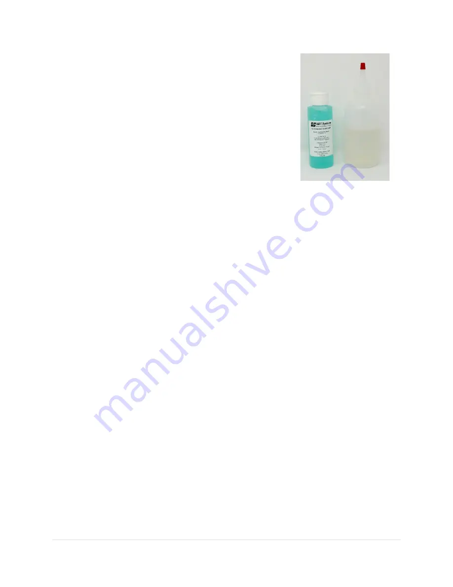
A liquid couplant film is always needed to transfer the high
frequency ultrasonic energy between the probe and the material. Typically,
couplant is generously applied to the material surface, although it sometimes
can be initially applied to the bottom of the probe (as during some high
temperature applications). The type of couplant used is very important for
optimum performance.
Smooth material surfaces require a lower viscosity couplant, such as water,
glycerin or grease as necessary. Special high temperature couplants should be
used on surfaces above 175 deg F.
NDT Systems offers numerous ultrasonic couplants which cover virtually all
application areas for the TG110DL. These specially formulated couplants should
be used whenever possible.
Reference Samples:
To calibrate the TG110DL, a known thickness or a known ultrasonic velocity for the material is
needed. These calibration techniques require. at least initially, a reference sample representing the material to be
gauged. The closer the reference sample matches the actual material, the better the gaging accuracy. To
compensate for calibration factors, such as material composition (most important), micro-structure heat treat
condition (alloys), grain direction (alloys), thickness ranges, surface roughness and contour, the 'ideal' reference
material would come from pieces of the actual material. This type of reference sample is used for critical
applications for those requiring maximum gaging accuracy.
For most applications, satisfactory gaging accuracy can be obtained by using a single reference sample. This sample
should have the same composition and same nominal thickness (measured within required tolerances) as the
actual material/product. The material or product itself is often used with a micrometer to accurately measure an
accessible representative thickness.
When gaging thin materials that approach the lower performance limits of the gauge/probe combination,
experiment with reference samples to determine the actual lower limit. Do not gauge materials thinner than this
limit (See Gaging Precautions).
If a thickness range is anticipated, then use a reference sample that represents the thicker end of the range.
For exceptionally large thickness ranges, particularly in alloys where micro structural variations occur, use separate
samples and calibration setups at selected intervals across the range.
Many wrought and cast metal microstructures exhibit directionality that, depending upon the beam direction.
causes a slight variation in ultrasonic velocity. For improved accuracy, reference samples should have the same
directionality/sound beam orientation as that of the material to be gauged.
A machined step-wedge is a commonly used and convenient reference sample that has thicknesses across the
range of interest (flat steps for flat materials or concentric steps for smaller-diameter tubing).
Under certain conditions, the published ultrasonic velocity value for a given material (see velocity table in
appendix) can be used instead of a reference sample. Such a procedure is only satisfactory if the material has a
known and constant velocity and the intended application does not require relatively high gaging precision. This
approach is reasonable for many of the simpler, more-rugged applications involving the gaging of mild steel (plain
carbon steel). In some cases. published velocity values will be found to differ appreciably depending upon the
source of the publication. This is due to inherent material chemical/physical variations. Published velocity data
tend to be useful only where approximate or relatively coarse thickness gaging precision is acceptable.


