background image

1. - (negative) connection from the starter battery. 
2. - (negative) connection of the leisure battery. 
3. + (positive) connection from the starter battery. 
4. D+ Signal from the alternator or i signal line.  
5. AUX:  connection  of  the  existing  control  unit 

(sargent, schaudt, etc.). 

6. Output  of  the  charger  (connects  to  the  positive 

terminal of the leisure battery). 

7. Solar  panel  direct  connection  12V  nominal 

(maximum  voltage    with  open  circuit  lower  than 

28V). 

8. Debug and update connection (NDS internal use). 
9. IEC  socket  for  the  connection  of  the  mains  power 

supply (Only for GOLD series). 

SPECIFIC  AUX  CONNECTION  (PIN  NO.  5)  FOR  THE 

FOLLOWING  MODELS:  PLUS  25,  PLUS  30,  PLUS  40, 

PLUS 24-24/20, GOLD 25-M, GOLD 30-M, GOLD 40-M, 

GOLD 24-24-M 

POWER

SERVICE 

has  an  auxiliary  terminal:  (terminal 

n°5)  dedicated  to  the  original  control  unit  output  (eg 

CBE, Sargen, Schaudt, nord elettronica) or to the split-

charge  relay.  This  Terminal  is  used  to  connect 

appliances such as the fridge, lights, pump, etc. All the 

cables  that  were  originally  connected  to  the  leisure 

battery’s positive terminal should be connected to this 

auxiliary input (5). 

14

NOTE  

The  negative  pins  n°1  and  2  are  internally  connected  to 

each 

Summary of Contents for POWERSERVICE GOLD 12-24-M

Page 1: ... 1 POWERSERVICE User Manual ENGLISH VALID FOR THE FOLLOWING MODELS PLUS 25 PLUS 30 PLUS 40 PLUS 12 24 20 PLUS 24 24 20 GOLD 25 M GOLD 30 M GOLD 40 M GOLD 12 24 M GOLD 24 24 M ...

Page 2: ...he European Directive 2012 19 EU according to the local waste disposal rules do not dispose of old products with normal household waste The proper disposal of products that can no longer be used prevents potential negative consequences for the environment and for the population ...

Page 3: ...OPERATION 6 5 LED INDICATORS 9 6 CHARGING CURVES 10 7 CONNECTIONS 13 8 INSTALLATION 16 9 WIRING DIAGRAMS 19 10 CHECKING THE SYSTEM S OPERATION 24 11 MAINTENANCE 26 12 FUSE REPLACEMENT 27 13 TROUBLESHOOTING 29 14 TECHNICAL FEATURES 31 15 F A Q 39 16 WARRANTY 42 ...

Page 4: ...n very humid environments in contact with water splashes various liquids or exposed to rain To avoid risk of electric shock and or fire the vehicle s fuel system must be in good condition in case of damaged connecting cables or inadequate section immediately replace them with suitable cables as specified by this manual or by a qualified electrician in case of anomalies in the conformity of the pro...

Page 5: ...ollowing models 3 NOTE It is indispensable for a correct installation to be equipped with suitable measuring instruments Multimeter with DC voltage measurement 20V or autoscale and continuity measurement Amperometric clamp with direct current measurement 40A scale and higher INPUT 12V OUTPUT 12V PRODUCT CODE PLUS 25 PLUS 26 PLUS 27 GOLD 25 M GOLD 30 M GOLD 40 M INPUT 24V OUTPUT 24V PRODUCT CODE PL...

Page 6: ... the shortest possible time POWERSERVICE allows you to correctly charge one or more leisure batteries with capacities exceeding 75Ah to maximum power making the most of all available sources of energy on a motorhome or camper van POWERSERVICE includes two advanced models tailored for modern recreational vehicles needs PLUS CHARGER DC DC charges from alternator and solar panel GOLD CHARGER DC DC AC...

Page 7: ...Easy To Install The innovative circuitry in the POWERSERVICE unit guarantees greater efficiency by reducing energy expenditure output current is regulated both according to the needs of leisure batteries and to the quantity of input energy while travelling the device gradually reduces the output current in the event that the alternator is in overload conditions eg at night with lights on air condi...

Page 8: ...harging phases operate independently from the input energy source and for each phase the voltage and current supplied are 6 PROTECTION TYPE REACTION TYPE Battery over voltage Charge is interrupted Alternator overload Power Service automatically shuts off if the input voltage from the alternator and or the engine battery falls below 12 8V Over temperature Reduces the output current and turns off au...

Page 9: ... supply or overload by the alternator intervening promptly if necessary reducing the output current or stopping the charge completely the output current is limited if the POWERSERVICE detects an active signal D or ignition and starter battery voltage below 13V the device switches off completely if it detects a voltage of 12 8V at the starter battery or if the signal D or Ignition ie engine shutdow...

Page 10: ...stops charging using the solar controller when the panel voltage becomes lower than the leisure battery there is not enough light to sustain a charging current POWER SUPPLY FROM 230V MAINS CONNECTION GOLD SERIES ONLY If the ignition or D signal is not active and the power supply is connected and active the POWERSERVICE GOLD gives priority to the mains power supply and stops using the solar panel T...

Page 11: ...source of incoming charge and the charge phase that the device is using the charging phase in progress is shown with a corresponding number of flashes on the relevant LEDs 9 NOTE All the led signals are at page 28 GOLD solar panel grid 230v ALTERNATOR PLUS SOLAR panel ALTERNATOR ...

Page 12: ...ms with smart alternators and LiFePO4 lithium batteries The charge curves are selectable using two jumpers A Curve AGM B Curve GEL 10 YES NO MODEL 12V 24V Max voltage 14 8V 29 6V Float voltage 13 8V 27 6V Max desulfation voltage 15 8V 31 6V YES YES MODEL 12V 24V Max voltage 14 3V 28 6V Float voltage 13 6V 27 2V Max desulfation voltage 15 8V 31 6V ...

Page 13: ...oat voltage 13 5V 27V Max desulfation voltage not allowed MODEL 12V 24V Max voltage 14 6V 29 2v Float voltage 13 7V 27 4V Max desulfation voltage not allowed NO NO CAUTION The D curve is specific for euro 6 engines with smart alternators and entails a delay of several seconds for the activation of the system wait until the end of the procedure ...

Page 14: ... maximum voltage desulfa tion maintenance Vmax Imax Imax 2 1 2 3 V I 5 t maximum current maximum voltage maintenance NOTE During charging the device s led indicators will emit flashes corresponding to the charging phase being used at the time the various phases are indicated at the base of the above graphs ...

Page 15: ...7 CONNECTIONS The device has a seven 7 terminal block for power connections for cables up to 16mm2 13 GOLD Z 9 1 2 3 4 5 6 7 8 PLUS 1 2 3 4 5 6 7 8 ...

Page 16: ...nal use 9 IEC socket for the connection of the mains power supply Only for GOLD series SPECIFIC AUX CONNECTION PIN NO 5 FOR THE FOLLOWING MODELS PLUS 25 PLUS 30 PLUS 40 PLUS 24 24 20 GOLD 25 M GOLD 30 M GOLD 40 M GOLD 24 24 M POWERSERVICE has an auxiliary terminal terminal n 5 dedicated to the original control unit output eg CBE Sargen Schaudt nord elettronica or to the split charge relay This Ter...

Page 17: ...ll be free of loads allowing the POWERSERVICE to further accelerate the charge while driving In case of vehicles without a control unit self build vehicles for example and or a vehicle with the electrical system being installed for the first time the AUX input Pin n 5 will have the same operation indicated above It is always advisable to install an external split charge relay since it guarantees t...

Page 18: ... with fabric or carpet Install the device as close as possible to the leisure batteries POWERSERVICE can work in any position if installed on a vertical wall it is recommended to keep the short side parallel to the floor with connections downwards Do not install the device close to sources of heat or in a place that is not adequately ventilated and that could rea ch ver y high temperatures eg en g...

Page 19: ... positive pole of the leisure battery and connect them to pin N 5 of the POWERSERVICE Not valid for models PLUS 12 24 and GOLD 12 24 8 Connect the leisure battery positive pole to Pin N 6 of the POWERSERVICE 9 Connect the D or ignition signal wire to the POWERSERVICE Pin n 4 10 Only for GOLD models connect the 230VAc mains supply to the input IEC connector Link the connection after the general sys...

Page 20: ...e POWERSERVICE 18 NOTE The data connector placed on the right of the power connector is for technical use it is strictly forbidden to connect any device in this socket any tampering could irreparably damage the appliance Use cables with a cross section of at least 10mm2 for connections between engine battery and Power Service and in the output towards the leisure battery if the distance between th...

Page 21: ... CHARGE RELAY 19 FOR CABLES LONGER THAN 2 METERS USE 16mm2 CABLES In this case for ordinary vehicles to be transformed to RV or v e h i c l e s t h a t n e e d a n a u x i l i a r y b a t te r y t h e POWERSERVICE can be used to manage the charge and the distribution of energy ...

Page 22: ...ROL UNIT CHARGING SYSTEM 20 FOR CABLES LONGER THAN 2 METERS USE 16mm2 For the control unit we mean the unit of control and distribution of energy on the HABITATION PART of the vehicle Eg CBE ds300 Schaudt EBL163 nord elettronica ne287 SARGENT BCA etc ...

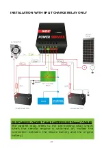
Page 23: ... RELAY ONLY 21 FOR CABLES LONGER THAN 2 METERS USE 16mm2 CABLES The parallel relay refers to the pre existing relay which when the vehicle engine is switched on makes the connection between the leisure battery and the engine battery ...

Page 24: ...PLUS AND GOLD 12 24 M INSTALLATION IN VEHICLE WITH 12V ALTERNATOR AND 24V SERVICE LEISURE BATTERIES 22 FOR CABLES LONGER THAN 2 METERS USE 16mm2 CABLES ...

Page 25: ...ANAGER IN SYSTEMS WITH TWO LEISURE BATTERIES 23 FOR CABLES LONGER THAN 2 METERS USE 16mm2 CABLES The POWERSERVICE output must be connected to the common positive of the i manager in order to supply the two leisure batteries ...

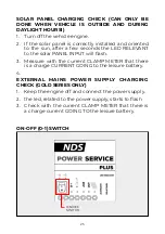
Page 26: ...that the leisure battery s voltage is greater than the previously measured value 5 Wait for two flashes of the device LED followed by a pause and check with a current CLAMP METER that the charge current is equal to the maximum current of the POWER SERVICE UNIT this phase could last a few seconds if the leisure battery is completely charged 6 With a multimeter measure the voltage on the starter bat...

Page 27: ...o the solar PANEL INPUT will flash 3 Measure with the current CLAMP METER that there is a charge CURRENT GOING to the leisure battery 4 EXTERNAL MAINS POWER SUPPLY CHARGING CHECK GOLD SERIES ONLY 1 Keep the engine off and connect the power supply 2 the led related to the power supply starts to flash 3 Check with the current CLAMP METER that there is a charge current GOING TO the leisure battery ON...

Page 28: ... should be set to OFF 0 only if the device malfunctions disconnecting it when the engine is switched on and allowing the battery to be charged using the alternator directly using the original system 11 MAINTENANCE The POWERSERVICE requires minimal maintenance to continue operating properly we periodically recommend Clean externally to prevent accumulation of dust and dirt Check that the input conn...

Page 29: ...cted but feature fuse protections for each of the input and output terminals To access the DC part fuse you must unscrew 4 side screws 2 on each side and lift the front cover taking care not to damage the wires connected to the leds and to the switch 27 1 2 3 4 6 5 ...

Page 30: ...panel line pin n 7 non for 24V output models 25A blade fuse 7 Main power supply IEC socket only GOLD series 10A glass fuse Type 5x20 NOTE All the connection pins you can find in the upper table are explained at page 14 chapter 7 connections Fuses 4 and 5 are connected in parallel and they are connected both to pin n 6 By replacing the fuses the POWERSERVICE will perform an automatic restart In cas...

Page 31: ...tegrity of the 2 x 25A fuses at the out pin 2 Check for any faulty contacts 3 Check that the solar panel voltage pin 7 is less than 28V 4 Wait for the system to cool down 5 Restart the device at full speed with battery not fully charged PROBLEM POTENTIAL CAUSES Alternator and solar panel leds are on continuously External temperature detected under 2 C SOLUTION It s a security system in case of cha...

Page 32: ...mm2 min section 2 Check the connections on terminals 1 2 3 and 6 3 Connect the cable attached to terminal 1 directly to the negative pole of the engine battery or services 4 Cable attached to terminal 2 directly to the negative pole of the leisure battery or motor 5 The cable relative to terminal 3 to the positive pole of the engine battery or positive pole of the alternator 6 The cable relative t...

Page 33: ...A Input Sources Recommended Power Alternator 70A 90A 110A Solar Panel 250W Nominal Output Voltage 12V Output Voltage Range 11V 16V Battery Output Numbers 1 Max Charging Current Alternator 25A 30A 40A Solar Panel 15A Galvanic Insulation No Maximum Efficiency 93 92 92 Cooling Cooling fan Charging Curves 5 Phases Charging Curve Selector Yes Jumper Battery Technology AGM GEL Flooded LiFePO4 Recommende...

Page 34: ...12 4V and D on Solar Panel Vp 16V and D off Deactivation Threshold Alternator Vm 12 8V or D off Smart Alternator Vm 11 8V or D off Solar Panel Vp vbs or D on Connections 7 Pole screw terminal block Status Indicator Yes 2 LED e Buzzer Protection Degree IP20 Protections Short circuit Reversed polarity Overheating Working Temperature 20 C 50 C Size 225mm x 135mm x 51mm Weight 950g NOTE For more detai...

Page 35: ... Panel Input Sources Recommended Power Alternator 110A Solar Panel Nominal Output Voltage 12V 24v Output Voltage Range 22V 32V Battery Output Numbers 1 max charging current Alternator 20A Solar Panel Galvanic Insulation No Maximum Efficiency 83 90 Cooling Cooling fan Charging Curves 5 phases Charging Curve Selector Yes Jumper Battery Technology AGM GEL Flooded LiFePO4 Recommended Battery Capacity ...

Page 36: ...2 4V and D on Vm 24 8V and D on Solar Panel Deactivation Threshold Alternator Vm 12 8V or D off Vm 25 6V or D off Smart Alternator Vm 11 8V or D off Vm 23 6V or D off Solar Panel Connections 7 Pole screw terminal block Status Indicator Yes 2 LED and Buzzer Protection Degree IP20 Protections Short circuit Reversed polarity Overheating Working Temperature 20 C 50 C Size 225mm x 135mm x 51mm Weight 9...

Page 37: ...3Hz Maximum Input Voltage Alternator 28A 34A 45A Solar Panel 15A Grid 3 5A Input Sources Recommended Power Alternator 70A 90A 110A Solar Panel 250W Grid 450W Nominal Output Voltage 12V Output Voltage Range 11V 16V Battery Output Numbers 1 Max Charging Current Alternator 25A 30A 40A Solar Panel 15A Grid 20A Galvanic Insulation Not from DC Yes from AC Maximum Efficiency 93 92 92 Cooling Cooling fan ...

Page 38: ...Activation Threshold Alternator Vm 13 3V and D on Smart Alternator Vm 12 4V and D on Solar Panel Vp 16V and D off Grid Presenza rete and D off Deactivation Threshold Alternator Vm 12 8V or D off Smart Alternator Vm 11 8V or D off Solar Panel Vp vbs or D on Grid Grid unavailable or D on Connections 7 Pole screw terminal block Status Indicator Yes 2 LED and Buzzer Protection Degree IP20 Protections ...

Page 39: ...olar Panel Grid 3 5A Input Sources Recommended Power Alternator 110A 55A Solar Panel Grid 450W 450W Nominal Output Voltage 24V Output Voltage Range 22V 32V Battery Output Numbers 1 Max Charging Current Alternator 20A Solar Panel Grid 10A Galvanic Insulation No Maximum Efficiency 83 90 Cooling Cooling fan Charging Curves 5 phases Charging Curve Selector Yes Jumper Battery Technology AGM GEL Flooded...

Page 40: ... 4V and D on Vm 24 8V and D on Solar Panel Grid Grid available and D off Deactivation Threshold Alternator Vm 12 8V or D off Vm 25 6V or D off Smart Alternator Vm 11 8V or D off Vm 23 6V or D off Solar Panel Grid Grid unavailable e D on Connections 7 Pole screw terminal block Status Indicator Yes 2 LED and Buzzer Protection Degree IP20 Protections Short circuit Reversed polarity Overheating Workin...

Page 41: ...e at the leisure battery rises above 15 8 16V is this normal This is normal during the desulfation phase 5 How long is the desulfation phase Desulphation has a variable duration depending on the length of the general charge It can last up to 2 hours 6 It is possible to connect a remote control to the POWERSERVICE No it is not possible to use a remote control to control or display the functioning o...

Page 42: ... to the observance of the following norms EN55022 2010 EN55024 2010 A1 2015 EN61000 3 2 2014 EN61000 3 3 2013 Compliance for the restriction of the use of hazardous substances is demonstrated in compliance with Directive 2011 65 EU RoHS 2 according to the law EN 50581 2012 40 Commercial Name POWER SERVICE Models PLUS 25 PLUS 30 PLUS 40 PLUS 12 24 20 PLUS 24 24 20 Company NDS ENERGY S R L Address V...

Page 43: ...EN61000 3 2 2014 EN61000 3 3 2013 Related to the electrical security BT Directive 2014 35 EU the conformity demonstrated to the observance of the following norms EN60335 1 2012 A11 2014 Compliance for the restriction of the use of hazardous substances is demonstrated in compliance with Directive 2011 65 EU RoHS 2 according to the law EN 50581 2012 41 Company NDS ENERGY S R L Address Via giovanni p...

Page 44: ... ndsenergy it tel 39 085 4470396 fax 39 085 9112263 STAMP AND SIGNATURE OF THE SELLER WARRANTY COUPON MODELS__________________________________________________________ SERIAL NUMBER____________________________________________________ PURCHASE DATE____________________________________________________ ...

Page 45: ...43 ...

Page 46: ...44 ...

Page 47: ......

Page 48: ...I SERVE ALL THE ENERGY YOU NEED 0011_MANU_PlusGold_GB01 NDS ENERGY S R L Via Pascoli 169 65010 Cappelle sul Tavo Pe Italy Tel 39 085 4470396 Web www ndsenergy it Email customer ndsenergy it LIKE US facebook com ndsenergysrl ...

Reviews: