background image

NCR RealScan 7872 Installation/Owner Guide

08/04

497-0415291    Release F

12 of 44

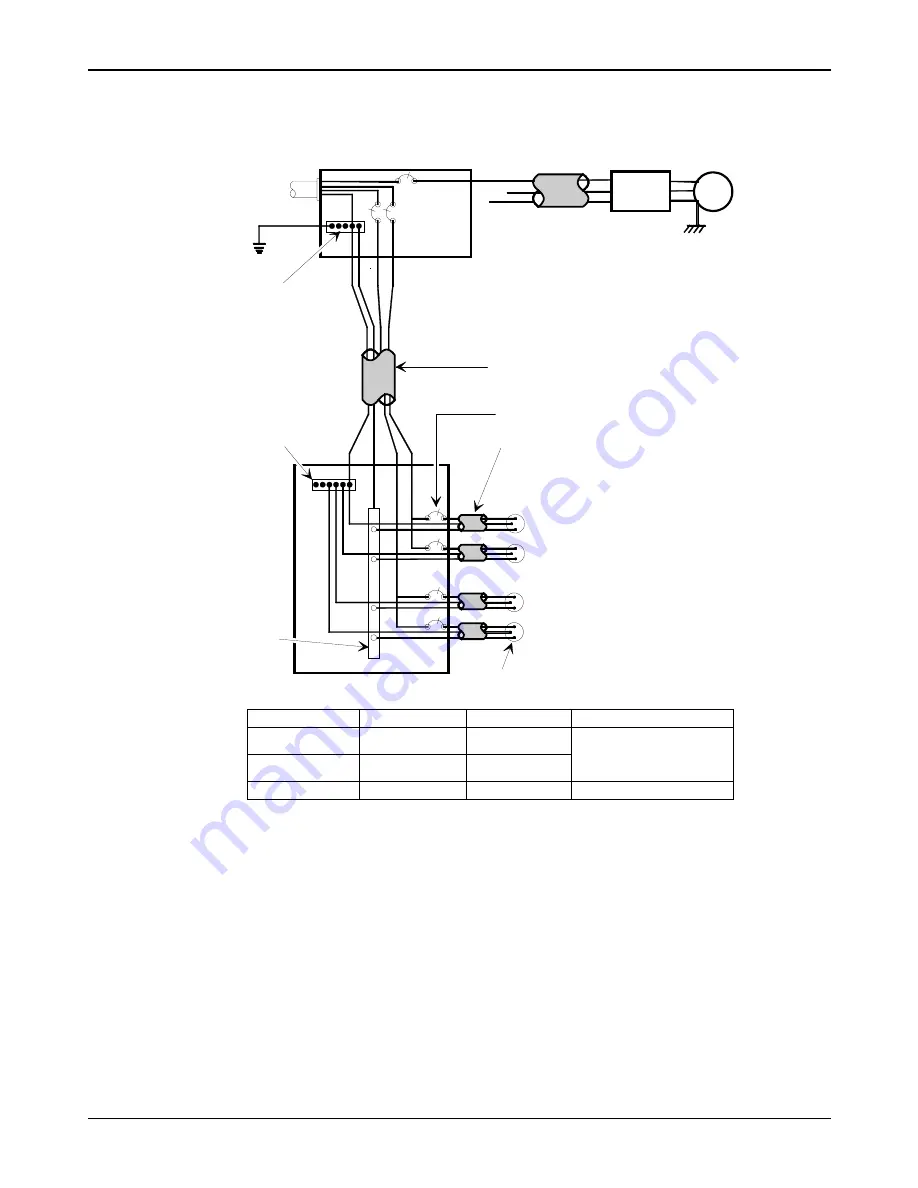
Electrical Wiring to the Checkstand

Feeder wiring and insulated ground from

main service panel to distribution panel

to be run in metal conduit.

The electrical wiring must meet all

electrical codes, laws, and regulations.

Note:

Circuit Breakers

NCR circuits should be run in

separate metal Conduits.

Isolated/Insulated

Ground Bus

Isolated Ground Receptacles

Neutral and

Ground Bus

Neutral

Bus

Input

Voltage

Input Voltage

L1, L2

Circuit Breakers

U.S., Canada, &

Japan

European

International

100Vac to 120Vac

220Vac

220Vac to 240Vac

100Vac to 120Vac

220Vac

220Vac to 240Vac

Standard single-pole; value

determined by type of device

branch and by electrical code.

European double-pole.

Circuit B: Terminal

Installation Type

NCR circuits must be dedicated to

NCR equipment or other logically

connected electronic equipment

(modems, DAA, bridges, etc.)

Note:

Circuit C: Scanner/Scale

Receptacle should be easily

accessible and near the

Scanner/Scale

L2

L3

Distribution Panel

Main Service

Panel

Conduit

Checkstand

Frame

Circuit A: Checkstand

Belt

Motor

Belt Control

Lighting

Misc. Equip.

N

G

L1

R0121

The RealScan 7872 outlet in the checkstand must be connected to a circuit breaker

switch. This switch must be located close to the operator and is used as the On/Off

switch for the RealScan 7872.

Summary of Contents for RealScan 7872

Page 1: ...RealScan 7872 Installation Owner Guide 497 0415291 Release F August 30 2004 Information Products RSD Atlanta...

Page 2: ...All features functions and operations described herein may not be marketed by NCR in all parts of the world In some instances photographs are of equipment prototypes Therefore before using this docume...

Page 3: ...15291 Release F 08 04 3 of 44 Preface Audience This book is written for hardware installer service personnel system integrators and field engineers References NCR RealScan 7872 User Guide B005 0000 11...

Page 4: ...the Scale 28 Cleaning the RealScan 7872 29 Correcting Scanner Problems 30 Correcting Scale Problems 31 Isolating Bizerba Scale Problems 32 Setting the Communication Protocol 33 Good Read Tone 34 Prog...

Page 5: ...cord Issue Date Remarks A June 2000 First Issue B Aug 2000 Update to diagrams and worksheets C 05 08 01 Updated checkstand cutout dimensions D 02 06 03 Added USB Connection and other miscellaneous inf...

Page 6: ...g the RealScan 7872 Installing the RealScan 7872 consists of five main steps Depending on the installation other information is sometimes needed It is recommended that you follow the installation step...

Page 7: ...for spilled liquids The RealScan 7872 must NOT be supported by this shelf E A Scanner Unit Actual Dimensions MODEL A B C D E 12xx 29 21 cm 11 1 2 in 50 80 cm 20 in 16 15 cm 6 3 8 in 3 33 cm 1 5 16 in...

Page 8: ...872 53xx 52xx 18151 C B F E A D G 2 5 cm 1 0 in side supports are optional instead of shelf Scanner Unit Actual Dimensions MODEL A B C D 53xx 29 21 cm 11 1 2 in 39 88 cm 15 11 16 in 16 15 cm 6 3 8 in...

Page 9: ...MODEL A B C D 03xx 05xx 29 21 cm 11 1 2 in 29 46 cm 11 9 16 in 16 15 cm 6 3 8 in 8 89 cm 3 1 2 in Fits 7870 3000 29 21 cm 11 1 2 in 34 36 cm 13 1 2 in 16 15 cm 6 3 8 in 12 70 cm 5 in Fits PSC 381 29 2...

Page 10: ...Service Clearance A 8 0 in 20 3 cm minimum if checkstand structure is not removable for servicing 1 0 in 2 5 cm minimum if checkstand structure is removable for servicing B 14 0 in 35 6 cm minimum if...

Page 11: ...thout an exhaust fan in the checkstand however there must be adequate convection airflow The ambient temperature inside the checkstand cannot be higher than 40 C 104 F Also the ambient temperature ins...

Page 12: ...0Vac 220Vac 220Vac to 240Vac 100Vac to 120Vac 220Vac 220Vac to 240Vac Standard single pole value determined by type of device branch and by electrical code European double pole Circuit B Terminal Inst...

Page 13: ...harp edges to cut the cable The following table gives the minimum hole size for each of the RealScan 7872 cables Cable Cable Length Minimum Hole Size Power Cord Outlet to Power Supply 3 05 meters 10 f...

Page 14: ...cables 3 Pass the interface cable through the checkstand opening See previous section regarding Hole Requirements for Cables 4 If you are installing an NCR 7825 Remote Display pass the cable from the...

Page 15: ...Adapter box must be located close to the RealScan 7872 The Display Data Cable 497 0404334 is 1 meter 39 4 inches long Attach the Communication Adapter box in a suitable position where it remains dry...

Page 16: ...1416 C313 0040 or you can make your own If you make your own it should be approximately 39 inches 1 meter long with 8 pin phone type connectors on each end J1 P1 16046 1 2 3 4 5 6 7 8 1 2 3 4 5 6 7 8...

Page 17: ...do not have a handle on the front to grasp pick up the unit by firmly grasping the tower with both hands by lowering the unit into the cutout placing it either on its side supports or on a shelf belo...

Page 18: ...to ensure scale accuracy Make sure that all supports are securely fastened and that the RealScan 7872 is sitting on all supports Communications Protocol The communications protocol strapping was set...

Page 19: ...rminals can cause interference that can invalidate the scale calibration You can calibrate the scale after power has been supplied for 30 minutes if the ambient temperature has been 20 C 68 F for at l...

Page 20: ...ng the unit off However if you do this you must still calibrate the scale before placing it into service Note The pound and kilogram weights used for calibration are not equivalent values They are the...

Page 21: ...accuracy when incrementally adding weight to the center of the top plate Use weights that correspond to the RealScan 7872 weight feature Step Weight Feature Add Weight Remove Weight Display Result 1...

Page 22: ...Remove Weight Display Result 1 13 995 kg 0 04 kg 30 0 lb 0 08 lb 2 13 995 kg 0 04 kg 13 995 0 005 kg 30 0 lb 0 08 lb 30 0 0 01 lb Note Do NOT remove any weight from the Top Plate Decreasing Load Test...

Page 23: ...the Cal and PAr values shown on the display Note Positions 1 is in the center of the Top Plate Positions 2 3 4 and 5 are halfway between the Top Plate center and the Top Plate corner 17707 1 2 3 4 5...

Page 24: ...isplay displays an error code and if available the RealScan 7872 emits an audible description of the error and what action to take Refer to the Correcting Scanner Scale Problems section for additional...

Page 25: ...lts identified by a heavy box that are determined at the factory Scanning the Default tag as the first tag after applying power to the unit sets the parameters to these values Changing the RealScan 78...

Page 26: ...RealScan 7872 is communicating with the host terminal The following are four good tags that you can use however the 7872 must be programmed to read these tags The default settings are UPC A enabled an...

Page 27: ...ponents The RealScan 7872 does not have a power switch However you turn it on and off by using the circuit breaker switch located in the checkstand that supplies power to the unit Be sure this switch...

Page 28: ...l zeros If not press the Scale Zero Button The item you are weighing should be placed in the center of the Top Plate Make sure the item does not overhang onto the checkstand whatever is weighed must f...

Page 29: ...ean Window indicator flashes when the scan windows need cleaning The window can be cleaned anytime it appears dirty or performance seems to be degrading To clean the scan window use a soft cloth moist...

Page 30: ...M terminal is recognizing the RealScan 7872 Verify that the Interface Cable is properly connected Scanner does not read tags Red Flashing Green Off Off Internal failure Remove power from the RealScan...

Page 31: ...y Program Mode Hex 3 Hex 0 Hex 4 Save and Reset 4 If error code persists have 7872 repaired 5 Scale drift 1 Verify that nothing is on the Top Plate 2 Lift the Top Plate and verify that no objects are...

Page 32: ...ed problem Refer to Correcting Scanner Problems chart Scanner Is Working Scale Not Working Scale problem Reset scale Remove power from the 7872 then apply power with no weight on the Top Plate Replace...

Page 33: ...the Hex 3 tag The good read tone for this tag sounds three beeps If the Voice feature enabled the communications protocol is given audibly If Voice is not enabled the Status indicator flashes green a...

Page 34: ...ccepted by the scanner In installations where the checkstand and operators are close together it is advantageous to alter the sound of the good read tone on each scanner This permits each operator to...

Page 35: ...ne unit Scan the End tag or a valid Hex tag to end this mode When entering Tone Length the adjustment can be incremented upward by scanning the Hex C tag Each time you scan the Hex C tag the tone leng...

Page 36: ...0 2 900 3 1050 4 1200 5 1350 6 1500 7 Restart Lockout Timer B Active Time Minutes C Off 0 On 1 0 0 15 1 30 2 60 3 13 Bar Codes 1 20556 UPC EAN Enable 1 0 Disable A Extend UPC A To EAN 13 C Extend UPC...

Page 37: ...37 of 44 14 Bar Codes 2 Code 39 Disable 0 Minimum Characters Allowed Full ASCII Check Digit Present Transmit Check Digit 2 F Default Allow One or Two Character Tags A B C D E F Enable 1 8 Disable 0 E...

Page 38: ...it Value 1 Characters Minimum Default Value 2 Characters Maximum Disable 0 A B C D Enable 1 Range Check 0 Specific Check 1 Character 1 0 3 Character 2 0 9 0 8 Default Character 1 0 3 Character 2 0 9 1...

Page 39: ...C 128 Emulation Mode 1 16 Label Identifiers Identifier Type None 2 0 Default Prefix A Common Byte 1 B Common Byte 2 C Bar Code Type D Common Byte 5 Default 0 UPC A Unique Prefix 3 Hex Character 0 7 He...

Page 40: ...Character 3 2 Stop Bits 8 Bit Character 0 RTS Low CTS Ignored 1 RTS High CTS Ignored 2 Raise RTS Wait for CTS 3 Raise RTS Ignore CTS 4 RTS Low Wait for CTS 5 RTS High Wait for CTS 21 RS 232 Parameters...

Page 41: ...or Byte is required on a scale unit If you select Disable it is ignored and an ETX 03 is sent Terminator Byte A ASCII Code Disable 0 0 7 0 Default Hex Character ASCII Code Chart Enable 1 B 0 F Hex Cha...

Page 42: ...71 72 73 74 75 76 77 78 79 7A 7B 7C 7D 7E 7F p q r s t u v w x y z DEL 60 61 62 63 64 65 66 67 68 69 6A 6B 6C 6D 6E 6F a b c d e f g h i j k l m n o 50 51 52 53 54 55 56 57 58 59 5A 5B 5C 5D 5E 5F P...

Page 43: ...NCR RealScan 7872 Installation Owner Guide 497 0415291 Release F 08 04 43 of 44...

Page 44: ...NCR RealScan 7872 Installation Owner Guide 08 04 497 0415291 Release F 44 of 44 Copyright 2000 2004 by NCR Corporation...

Reviews: