Leuze electronic BCL 608i, Operating Instruction
The Leuze electronic BCL 608i sets a new standard in automation technology. With its user-friendly design and advanced features, this cutting-edge product guarantees seamless operation. Enhance your experience with our comprehensive Operating Instruction manual, available for free download on our website. Unlock the full potential of the BCL 608i today.
Share
Download


Reviews:
No comments
Related manuals for BCL 608i

SC430
Brand: 3nStar Pages: 28

SC430
Brand: 3nStar Pages: 53

IMAGETEAM 3800i
Brand: Hand Held Products Pages: 32

Quickscan QD2200
Brand: Datalogic Pages: 235

PowerScan PM9100 Series
Brand: Datalogic Pages: 40
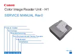
H1
Brand: Canon Pages: 112

U-P005
Brand: S4A Pages: 2

CS-WWT-10
Brand: clare Pages: 3

XT5-40 Series
Brand: BIXOLON Pages: 2

DR-12C
Brand: Rosslare Pages: 2

AY-x25B Series
Brand: Rosslare Pages: 3

AY-V12B
Brand: Rosslare Pages: 14

AY-Z12
Brand: Rosslare Pages: 16

KAEBK06TCHAA
Brand: Kogan Pages: 35

ATS1197
Brand: Interlogix Pages: 14

HT660 Wireless edition
Brand: Unitech Pages: 2

T50
Brand: Anviz Pages: 85

M-Class Mark II
Brand: Datamax Pages: 100


