background image

R E L A Y   P R O S  


[Date] 

Web Interface Connection


Gen 3 modules have a built-in web interface which may be 
utilized to configure settings in the module


To access the web 
interface simply open 
your web browser and 
enter the IP address of 
the Gen 3 module.  If 
you do not know the 
module’s IP address you 
may be able to discover 
it by opening the Base 
Station or Alpha Station 
software.  It is also 
possible to obtain the 
module’s IP address by 
checking the DHCP 
Table of your Router.  If 
your router does not 
support DHCP simply 
power the board down 
and install a jumper on 
the pins directly to the left of the Ethernet Jack, then power the board back 
up.  This will force the module to use a static IP address of 
192.168.1.88.  Note however that the module will not utilize user 
configured settings while this jumper is installed so be sure to power down 
the board and then remove the jumper once settings are entered as 
desired.  

Default Password


The Web interface is password protected.  The default password for the 
web interface is 

admin

.  


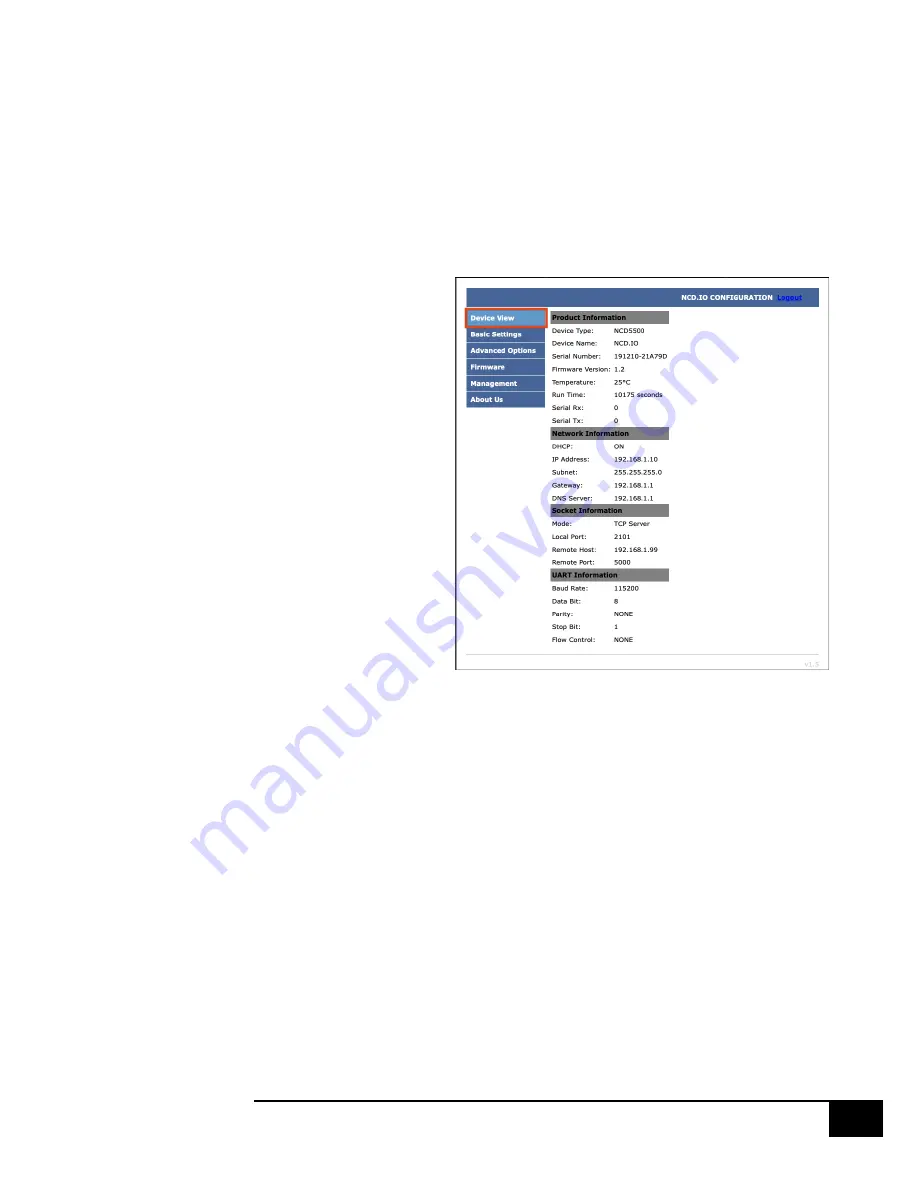
Device View 

The Device View page displays current information about the Gen 3 
Module such as its network connection information, its socket mode 
information, UART Settings, etc.   


Summary of Contents for Gen3 Ethernet Module

Page 1: ...GEN3 ETHERNET W N BUTTON Push Notification Quick Start Guide National Control Devices...

Page 2: ...ware will then send a text or email from the computer to your selected recipients All the Features You Need Send SMS or Email Message Compatible with ANY Contact Closure Sensor Dry Contact no voltage...

Page 3: ...module directly to the Ethernet port of your PC When configuring settings in this way you will need to leave the static IP address jumper in place alter the settings select Apply Settings power down t...

Page 4: ...oard Select Discovered Network Devices button then click on the IP Address this will open your browser and show you the Web Interface Connection and all its features By selecting the Discovered Networ...

Page 5: ...t support DHCP simply power the board down and install a jumper on the pins directly to the left of the Ethernet Jack then power the board back up This will force the module to use a static IP address...

Page 6: ...nored If you intend to enter Static IP address settings make sure this box is NOT checked IP Address This setting is only applicable if Use DHCP is unchecked This field configures the Static IP addres...

Page 7: ...ld configures the Port the module should attempt to establish a connection to on start up Local Port This field is only applicable when Socket Type is set to TCP Server This field configures the Port...

Page 8: ...efault password for the web interface is admin If desired you may change this password using the Password Setting Fields After the new password is set it will take effect after the next power cycle Fa...

Page 9: ...Button Communicating to the Board 1 Download and install the version of N Button Pro or N Button Lite that you purchased with the board Open N Button Then Click Device Manager You must add the board...

Page 10: ...le click the IP Address and the IP Address and Mac Address will populate the Network area above TCP UDP Port Keep default setting for TCP Port 2101 and UDP Port 3333 TCP Connection Check the TCP Conne...

Page 11: ...ch input on the board 1 Click the Scan Channel Button to open Properties Name Create a name Device The one you created Bank ID It will be 1 Channel ID The input you are reading with this widget Style...

Page 12: ...hen the dry contact circuit is closed You can now create a Scan Channel Widget for each of the inputs on the board then setup the automation to send the text and or email Testing Inputs Using a dry co...

Page 13: ...lick New in the Automation Manager Window to open the Rule Type Window Click Push Notification Contact Closure Rule 1 Select Settings under Push Notification Contact Closure to select the device you c...

Page 14: ...Under Action Type select Send Email You can also set a message for other actions such as when the contact closure opens to send a message when the circuit opens This will notify you wen the closure h...

Page 15: ...ith a comma Add your Subject and message Click OK in all open windows and return to the desktop 2 After finishing all previous page settings all recipients will receive an email once the contact closu...

Page 16: ...tton on the side of the Ethernet module for 5 seconds to reset the module back to factory settings 3 Use the NCD5500 Configuration Software for Windows to discover the device o Make sure that the IP a...

Page 17: ...e the NCD5500 Configuration Software for Windows to discover the device o Make sure that the IP address dropdown box in the top left of the NCD5500 Configuration software is set to your computer s ext...

Page 18: ...iscussions are welcome on applications and you are encouraged to share your experiences with other users Visit the community here community ncd io Serial Port Tool Questions for configuring N Button S...

Reviews: