


4-16
NBS Technologies Inc.
Creating Layouts
Chapter 4 Page 16
Guard Height
Ba
rc
od
e
Li
ne
s
Gu
ar
d
Li
nes
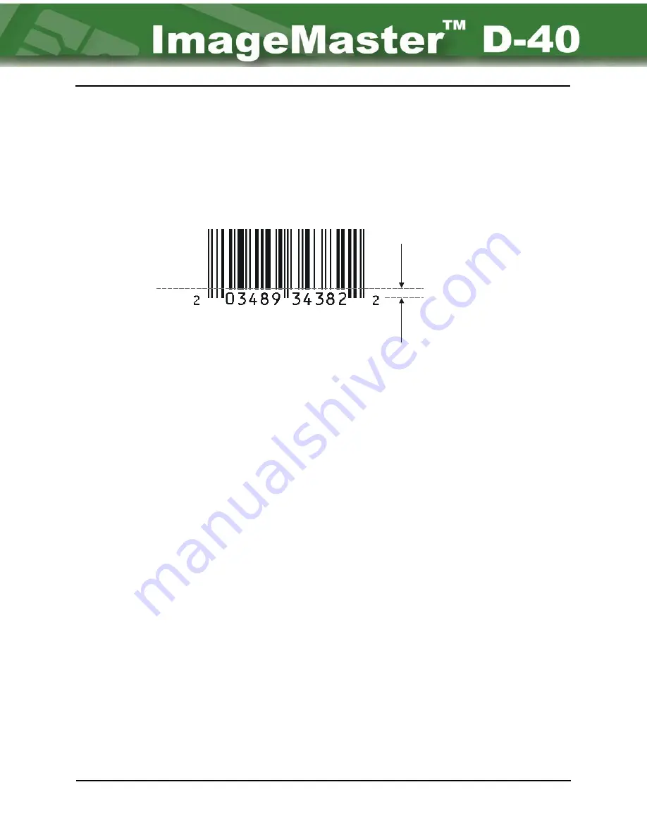
4.7.4: Guard Height
The “Guard Height” parameter is only available for UPC-A, NEW UPC-A, EAN 8, and EAN
13. “Guard Height” refers to the height of the guard lines. Guard lines are the portions of the
barcode that extends below and into the number field. (See Figure 4-14.) This parameter
allows the user to adjust and customize the height.
Figure 4-14
Guard Height Parameter
4.7.5: Ratio
“Ratio” is the width of a wide line vs. the width of a thin line. (
The “Ratio” parameter is not
available for UPC-A, or NEW UPC-A
.)
4.7.6: Density
“Density” is the parameter that controls the width of a thin line. Each bar can be one of four
possible thickness, varying from 1 module to 4 modules.
4.7.7: Gap
“Gap” is the parameter that controls the space between lines. Each space can one be of four
possible thickness, varying from 1 module to 4 modules.
4.7.8: Orientation
The “Orientation” parameter allows the
D-40
printer to print the barcode in any of the four
area directions around the X and Y Coordinates. These are: horizontal, vertical, reverse
horizontal, and reverse vertical. (
It should be understood that some barcodes cannot be read
backwards or upside down
.)


