background image


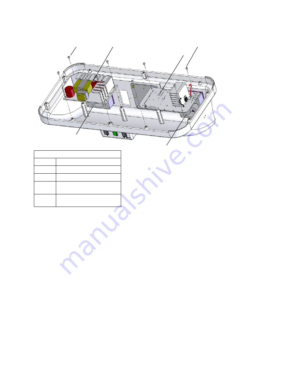
F

IGURE 

5-1


E

NCLOSURE AND ITS ATTACHMENTS


Item  

Description  

19 

Screw 1/4” 

4  

LED light current assembly 

5  

Power supply 

10 

Enclosure fan, Constant 
Current Board Side 

14 

Enclosure fan, Power Supply 
Side 


14 


19(x4) 


19(x4) 

10 

neoBLUE

®

 LED Phototherapy System Service Manual


33


PN 001320 Rev K 

Summary of Contents for neoBLUE

Page 1: ...Service Manual...

Page 2: ...rom Natus Medical Incorporated The content of this manual may change without notice Natus Medical Incorporated 5900 First Avenue South Seattle WA 98108 USA Telephone 1 650 802 0400 Fax 1 650 802 0401...

Page 3: ...ng Guide 20 3 1 Troubleshooting the neoBLUE light 20 3 2 Troubleshooting the LED light current assembly 23 Chapter 4 Repair Procedures 26 4 1 Removing the lens 27 4 2 Removing the LED light panel 28 4...

Page 4: ...two filters on backside of enclosure 14 Figure 2 2 Measuring distance 18 Figure 2 3 Adjusting the potentiometers 19 Figure 4 1 Removing the lens 28 Figure 4 2 Removing the LED light panel 29 Figure 5...

Page 5: ...r 3 Repair procedures Chapter 4 Parts and ordering information Chapter 5 Measuring the neoBLUE light with a radiometer Chapter 6 Electromagnetic Specifications Chapter 7 1 1 2 Intended users This serv...

Page 6: ...Important An instruction provided to help ensure correct clinical results and provide quality assurance to the phototherapy procedures Note Background information provided to clarify a particular step...

Page 7: ...n over their lifetime with proper use Nevertheless the user can adjust the output of the LEDs for any degradation using the two potentiometers Life testing has shown neoBLUE LEDs can emit high intensi...

Page 8: ...ntensity rocker switch Sets intensity to high or low 9 Target light rocker switch Controls red target light momentary action 33 On standby switch Lights up when device is on FIGURE 1 2 EXTERNAL REAR V...

Page 9: ...ludes fuses 12 Enclosure fan filter assembly Consists of a cover filter and backplate 29 Thumbscrew For attaching enclosure to roll stand 30 Locating post screw Slotted 34 Timer Counts hours device is...

Page 10: ...udes fuses 8 Light intensity rocker switch For selecting intensity level 9 Target light rocker switch Indicates center of treatment area 11 Vent Guard A Mounting plate Mounts light to roll stand 33 On...

Page 11: ...FIGURE 1 4 POWER SUPPLY s Item Description A 24 volt ground Pins 5 8 B 24 volts Pins 1 4 C AC inlet C B A neoBLUE LED Phototherapy System Service Manual 9 PN 001320 Rev K...

Page 12: ...anel header J8 B Main power fan header J2 C Front panel switch header J3 D Light intensity adjustment potentiometers E On standby header J4 F Timer power header J5 G Fan power header J6 H Timer reset...

Page 13: ...ions FIGURE 1 6 BLOCK DIAGRAM 1 4 Before you start WARNING Observe Electrostatic Discharge ESD precautions when handling adjusting or performing any procedure with the device internal components neoBL...

Page 14: ...uth Seattle WA 98108 USA Telephone 1 650 802 0400 Fax 1 650 802 0401 Technical Service 1 800 303 0306 Technical Service Fax 1 650 802 8680 E mail technical_service natus com Customer Service 1 800 303...

Page 15: ...UUT These procedures must be performed after any of the following events and or as prescribed by the institution s maintenance schedule Initial receipt of the UUT at the institution Foreign material o...

Page 16: ...ure and accessories Clean the UUT enclosure using a cloth dampened with Germiocide or an equivalent product Wipe the exterior plastic surfaces lightly Do not allow any liquid to penetrate the power co...

Page 17: ...ment and its application must comply with the applicable standard in Table 2 1 Ground Integrity Table 2 2 Earth leakage current Table 2 3 Enclosure leakage current TABLE 2 1 GROUND INTEGRITY 100 milli...

Page 18: ...nversion Chart in chapter 6 If the meter is not listed please contact Natus Technical Service before adjusting light intensity 2 3 1 Verifying general performance 1 Turn off the Illuminated On Standby...

Page 19: ...s operating The decimal point should be flashing if the device is on and not flashing when the device is off Turn off the UUT by turning off the Illuminated On standby switch 11 Check the light intens...

Page 20: ...light panel over the work pad 3 Place the radiometer on the work pad under the light panel The distance B should be measured from the work pad surface to the bottom of the lens 6 as shown in Figure 2...

Page 21: ...o the user Turn off the UUT and ignore all further steps in this chapter 7 If light intensity on either setting was not within tolerance leave the test setup as is and proceed to Section 2 4 on page 2...

Page 22: ...hapter assumes that you are a qualified biomedical technician who is familiar with the neoBLUE light 3 1 Troubleshooting the neoBLUE light When opening the device be sure to follow the procedures desc...

Page 23: ...y module Plug in Verify that the voltage coming out of the power inlet is between 90 132V or 210 260V depending on the power system used in your country Damaged power supply Verify that the power supp...

Page 24: ...warm verify that vents are not blocked Figure 2 1 on page 17 Fan not working Verify that both enclosure fans are functioning correctly If they are not refer to fan actions below Enclosure fan s not w...

Page 25: ...E and plug it into an appropriate AC power source Verify that the neoBLUE is getting the correct mains voltage at the power supply module input Ac voltage into the power supply should be 100VAC to 240...

Page 26: ...J1 6 J2 4 2 7 5 1 VDC HIGH setting 4 5 6 1 VDC LOW setting Target LED brightness J1 7 J2 4 4 0 VDC 1 0 VDC These voltages should vary within the ranges given as the adjustment potentiometers R3 HIGH...

Page 27: ...DC J4 3 J4 4 21 5 22 5 VDC J5 1 J5 3 23 5 24 5 VDC Switch in OFF position Pins Voltage range J4 1 J4 4 21 5 24 5 VDC J4 2 J4 4 0 0 0 1 VDC J4 3 J4 4 0 0 0 1 VDC J5 1 J5 3 0 0 0 1 VDC Failure of any of...

Page 28: ...e enclosure remove and or replace components or make adjustments If your medical facility does not have qualified personnel please contact Natus Technical Service for further assistance After any repa...

Page 29: ...he lens away from the enclosure Use caution The lens is tightly fitted on the enclosure 5 If you are replacing the lens obtain the replacement and reverse the steps above to install the lens Note that...

Page 30: ...stant current board by a power cable Do not attempt complete removal until the cable connector is removed from the receptacle on the light panel To remove the cable squeeze the release lock and pull u...

Page 31: ...ections discuss removal of the enclosure components which are shown in Figure 4 4 on page 30 Removing the enclosure fan on page 30 Removing the AC power entry module on page 30 Removing the switches o...

Page 32: ...ction 4 2 on page 28 until the UUR is completely assembled Return to Chapter 2 and perform the safety tests and performance verification and adjustment 4 3 2 Removing the AC power entry module 1 Obser...

Page 33: ...r of the enclosure 3 If a switch is being replaced Obtain the replacement and reverse these steps to install Reverse all steps in Section 4 2 on page 28 until the UUR is completely assembled Return to...

Page 34: ...y be required for spare parts The list of product specifications in this chapter will guide you in making purchases from vendors other than Natus 5 2 Parts in context Two views of the neoBLUE light ap...

Page 35: ...Item Description 19 Screw 1 4 4 LED light current assembly 5 Power supply 10 Enclosure fan Constant Current Board Side 14 Enclosure fan Power Supply Side 5 14 4 19 x4 19 x4 10 neoBLUE LED Phototherapy...

Page 36: ...nsity switch 22 Screw 1 3 4 9 Target rocker switch 24 Screw 5 8 10 Fan Enclosure Power Supply side 29 Thumbscrew 11 Vent guard 30 Locating post screw 1 2 Enclosure fan filter assembly 33 Illuminated o...

Page 37: ...re of the part or reference to a figure TABLE 5 1 PARTS LIST FOR NATUS NEOBLUE SYSTEM Item Qty Name Illustration 1 1 001088 LED light panel Figure 1 3 on page 8 2 1 040940 Enclosure Figure 1 2 on page...

Page 38: ...onnectors N a 16 1 001101 Cable Fan power supply 4 Conductor cable w 2 connectors and 2 lug rings N a 17 1 900073 Cable Tie 14 5 Nylon N a 18 1 001102 Cable LED light panel 10 Conductor cable w 2 conn...

Page 39: ...en 34 1 900831 Timer single display 35 1 040892 Cable Power for timer 2 conductors with 1 connector and 2 spade connectors 36 1 001097 Cable On standby switch 4 conductors with 1 connector and 4 spade...

Page 40: ...cifications FIGURE 5 4 ENCLOSURE ITEM 2 A Timer hole B Roll stand mounting plate C Illuminated switch hole FIGURE 5 5 LED LIGHT CURRENT ASSEMBLY ITEM 3 B C A 38 neoBLUE LED Phototherapy System Service...

Page 41: ...e User Manual and this Service Manual These manuals may be used online or printed out For best results print two sided in color Warranty statement TABLE 5 2 ACCESSORY PACK Item Qty Name Illustration 1...

Page 42: ...justable from 42 to 59 3 inches 1 07 m to 1 50 m 7 6 cm Center of lens from post adjustable from less than 9 to 13 1 inches 23 cm to 33 cm 2 5 cm Tilt adjustment of enclosure 0 horizontal to approx 40...

Page 43: ...LUE light to the desired intensity when changing the distance Because your facility may use a different radiometer to measure light intensity output it is necessary to understand how your reading corr...

Page 44: ...SPR 11 Group 1 The neoBLUE LED Phototherapy device uses RF energy only for its internal function Therefore its RF emissions are very low and are not likely to cause any interference in nearby electron...

Page 45: ...ions and voltage variations on power supply input lines IEC 61000 4 11 5 UT 95 dip in UT for 0 5 cycle 40 UT 60 dip in UT for 5 cycles 70 UT 30 dip in UT for 25 cycles 5 UT 95 dip in UT for 5 seconds...

Page 46: ...and TV broadcast cannot be predicted theoretically with accuracy To assess the electromagnetic environment due to fixed RF transmitters an electromagnetic site survey should be considered If the measu...

Page 47: ...ion distance d in meters m can be estimated using the equation applicable to the frequency of the transmitter where P is the maximum output power rating of the transmitter in Watts W according to the...

Reviews: