


Getting Started with NI SMD-7620/7621 and NI 9512 Modules
|
© National Instruments
|
15
6.
Click
Discover
in the
Discover C Series Modules?
dialog box if it appears.
7.
Click
Continue
.
8.
Right-click the controller item in the
Project Explorer
window and select
Properties
from
the shortcut menu to display the
RT Target Properties
dialog box. Select
Scan Engine
from the
Category
list to display the Scan Engine page.
9.
Set the
Scan Period
to 5 ms, then click
OK
to close the
RT Target Properties
dialog box.
10. Right-click the controller item in the
Project Explorer
window and select
New»
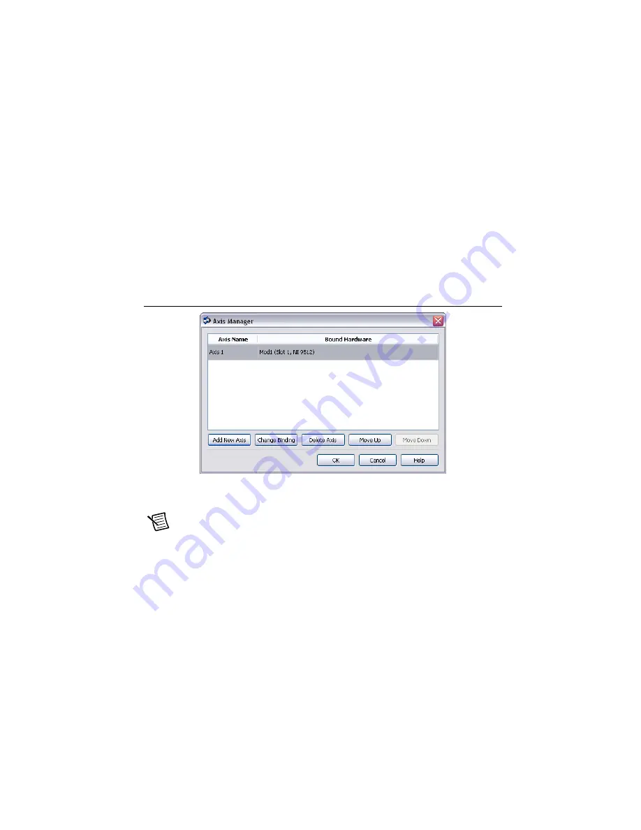
NI SoftMotion Axis
from the shortcut menu to open the
Axis Manager
dialog box, shown
in Figure 11.
11. Click
Add New Axis
to create an NI SoftMotion axis associated with the NI 9512 module.
Axes are automatically bound to an available module. You can double-click the axis name
to rename the axis and give it a descriptive name.
Figure 11.
Axis Manager Dialog Box
12. Click
OK
to close the
Axis Manager
dialog box. The new axis is added to the
Project
Explorer
window.
Note
You cannot associate more than one axis with the same C Series module.
When you have finished these steps your LabVIEW project should look similar to the
image in Figure 12.


