background image

12

|

ni.com

|

Getting Started with NI SMD-7620/7621 and NI 9512 Modules

Step 11: Power on the Drive and Verify Connections

After all hardware connections have been made complete the following steps to confirm the 
hardware setup.
1.

Turn on all power supplies and apply AC power.

2.

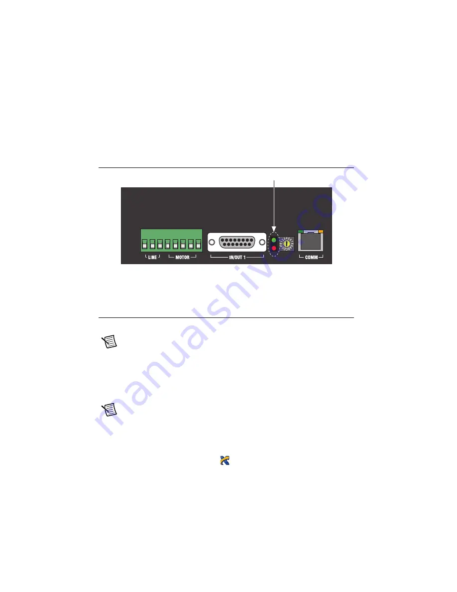
Verify that the Drive Status LED on the NI SMD-7620/7621 flashes or is solid green. 
Figure 10 shows the location of the Drive Status LED.

Figure 10.  

Drive Status LED Location

If the Drive Status LED does not flash or turn solid green, turn off all power, verify the 
connections, and try again. Refer to the 

Worldwide Support and Services

 section for additional 

tips.

Software Installation and Configuration

This section covers installing and configuring software for the NI 9512 C Series module.

Note

These instructions assume you have installed all required software from the 

What You Need to Get Started

 section on your development machine.

Step 1: Install Software on and Configure the NI RT 
Controller

Complete the following steps to configure the controller and install software on it.

Note

The Measurement & Automation Explorer (MAX) user interface may not 

match these steps exactly depending on which version of MAX you are using. 

Verify the NI RT Controller

1.

Launch Measurement & Automation Explorer (MAX) on the development computer by 
clicking the MAX icon on the desktop (

), or by szelecting 

Start»All Programs»

National Instruments»Measurement & Automation

.

S

t

a

t

us

 LED

s

Summary of Contents for NI SMD-7620

Page 1: ...t the 37 Pin Terminal Block to the 24 V Power Supply 6 Step 4 Connect the Drive Command Signals 7 Step 5 Connect the Drive Enable Signal 7 Step 6 Optional Connect the Drive Fault Signal 7 Step 7 Optio...

Page 2: ...781093 01 Separate 24 V power supply for the NI 9512 such as the NI PS 15 NI SMD 7620 7621 stepper drive NI or third party stepper motor Note NI offers stepper motors matched to the NI SMD 7620 7621 R...

Page 3: ...VIEW NI SoftMotion Module Help Use this help file to learn about using the NI SoftMotion Module in LabVIEW including information about function blocks and using the NI SoftMotion Module with the LabVI...

Page 4: ...DF by selecting Start All Programs National Instruments LabVIEW LabVIEW Manuals LV_Getting_Started pdf Hardware Installation and Configuration This section covers the hardware setup for the CompactRIO...

Page 5: ...hten the two captive screws on the front of the controller 2 Connect the controller to a power supply and an Ethernet network on the same subnet as the development computer Refer to the controller ope...

Page 6: ...the two Vsup inputs on the 37 pin terminal block The 37 pin terminal block provides a Vsup input for the NI 9512 on pin 14 and pin 22 2 Connect the V terminal from the 24 V power supply to one of the...

Page 7: ...d and I O Connector Step 5 Connect the Drive Enable Signal Complete the following steps to connect the Drive Enable signal which controls the enable function of the drive 1 Connect the X3 EN terminal...

Page 8: ...the line neutral and protective earth connectors as shown in Figure 5 2 Optional Install a fuse on the AC input line as shown The SMD 7620 contains an internal 8 A fast acting fuse The SMD 7621 conta...

Page 9: ...20 7621 Power and Motor Connector Step 9 Connect the SMD 7620 7621 to the Motor Caution Do not connect or disconnect the motor when the power is on NI offers NEMA 23 and NEMA 34 stepper motors matched...

Page 10: ...Figure 7 Figure 7 Eight Lead Motor Series Connection Note For information about connecting third party motors refer to the NI SMD 7620 7621 User Manual Figure 8 shows the NI SMD 7620 7621 motor connec...

Page 11: ...ne of the preset IP addresses or to the F position to configure the drive to use DHCP Note This document assumes you have configured the drive for DHCP For information about other settings refer to th...

Page 12: ...or additional tips Software Installation and Configuration This section covers installing and configuring software for the NI 9512 C Series module Note These instructions assume you have installed all...

Page 13: ...name and IP address 5 Click Format to start formatting the disk 6 When MAX finishes formatting the disk set the Safe Mode switch to the Off position and click OK 7 Select the System Settings tab on th...

Page 14: ...to display the Create Project dialog box You can also click the Create Project button on the Getting Started window The Create Project dialog box includes a list of templates and sample projects you...

Page 15: ...ick the controller item in the Project Explorer window and select New NI SoftMotion Axis from the shortcut menu to open the Axis Manager dialog box shown in Figure 11 11 Click Add New Axis to create a...

Page 16: ...dialog box includes configuration options for stepper drive command signals feedback devices motion and digital I O trajectory and axis setup Figure 13 shows the parts of the Axis Configuration dialo...

Page 17: ...do not have an encoder connected c Confirm that the Axis Enabled and Enable Drive on Transition to Active Mode checkboxes contain checkmarks These selections configure the axes to automatically activa...

Page 18: ...or button and make the following changes to enable NI SoftMotion to disable the drive and turn off the Drive Enable signal when the specified position error limit is exceeded Note The Monitor button i...

Page 19: ...t click the controller item in the Project Explorer window and select Deploy All to deploy the axis information 11 Select File Save Project to save the project Step 5 Configure the Drive Using the NI...

Page 20: ...onfiguration dialog box 1 Right click the axis in the Project Explorer window and select Interactive Test Panel from the shortcut menu Opening this dialog box sends the axis settings to the hardware a...

Page 21: ...ers Visit ni com services for NI Factory Installation Services repairs extended warranty calibration and other services Visit ni com register to register your National Instruments product Product regi...

Reviews: