


Getting Started with NI SMD-7620/7621 and NI 9512 Modules
|
© National Instruments
|
17
Note
The
Axis Configuration
dialog box user interface may not match this image
exactly depending on which version of the LabVIEW NI SoftMotion Module you are
using.
Complete the following steps to configure the axis I/O settings for use with the
NI SMD-7620/7621 stepper drive.
1.
Right-click the axis in the
Project Explorer
window and select
Properties
from the
shortcut menu to open the
Axis Configuration
dialog box.
2.
Configure the following settings on the
General Settings
page (
).
a.
Confirm that
Loop Mode
is set to
Open-Loop
. Axes configured in open-loop mode
produce step outputs but do not require feedback from the motor to verify position.
b.
Set
Feedback Source
to
Encoder 0
, if you have connected an encoder, or
None
if you
do not have an encoder connected.
c.
Confirm that the
Axis Enabled
and
Enable Drive on Transition to Active Mode
checkboxes contain checkmarks. These selections configure the axes to automatically
activate when the NI Scan Engine switches to Active mode.
Note
Disable these options to prevent axes from automatically activating when the
NI Scan Engine switches to Active mode.
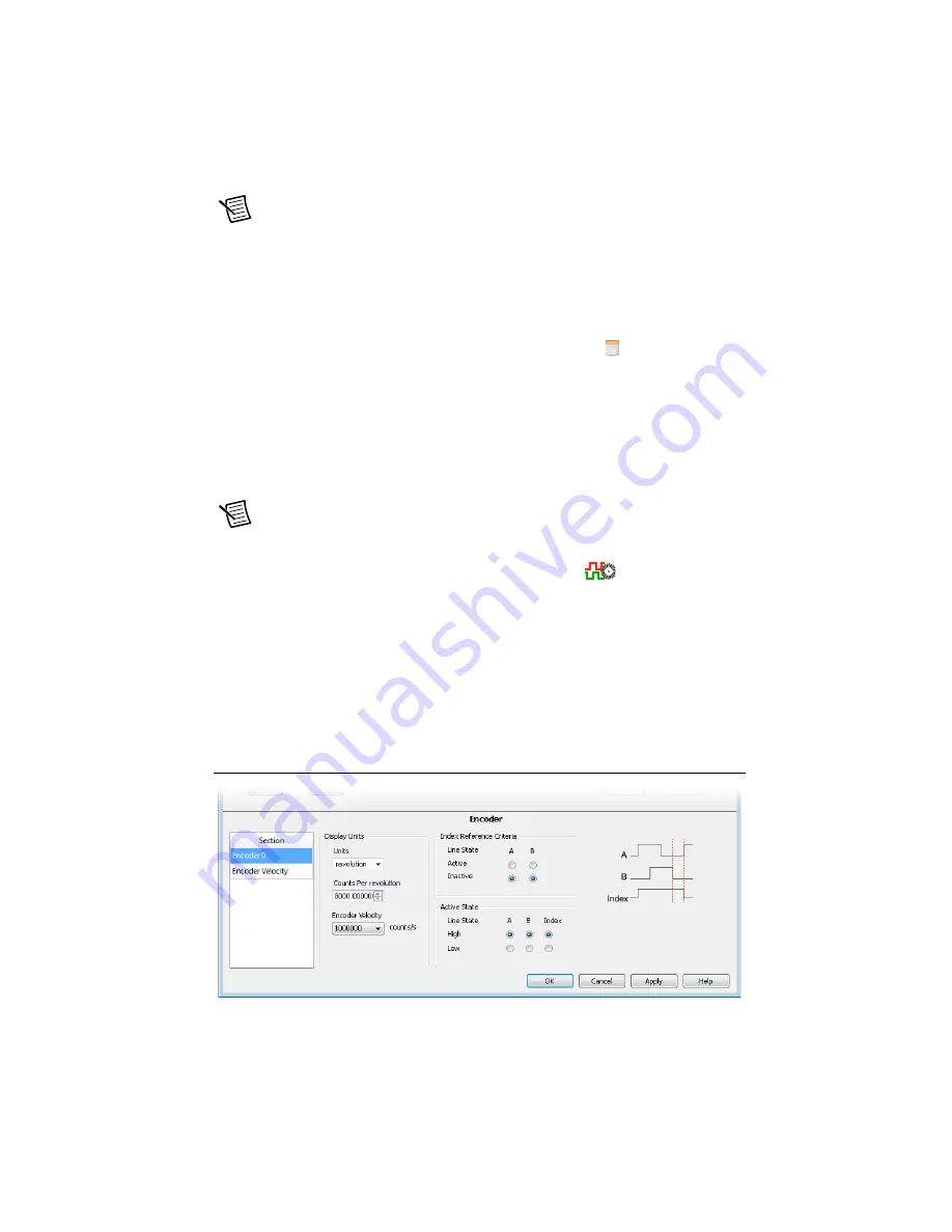
3.
If you have connected an encoder, click the Encoder button (
) and configure the
Units and Counts Per Unit.
a.
In the
Active State
section set the
Line State
for
A
,
B
, and
Index
to
High
.
b.
In the
Index Reference Criteria
section set the
Line State
for
A
and
B
to
Inactive
.
c.
Select
rev
from the
Units
text box, or type
revolutions
if you prefer.
d.
Set the
Counts per rev
to 8,000. This setting is the encoder resolution in quadrature
counts per revolution and corresponds to the encoder lines per revolution multiplied
by four.
When you are finished the Encoder Settings page will look similar to Figure 14.
Figure 14.
Axis Configuration Encoder Page


