NI 9144 User Guide and Specifications
|
© National Instruments
|
8
5
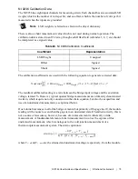
calibration conversion is performed on the module ADC itself, by applying the Gain and Offset
constants in the following equation:
where
y
represents the calibrated data for the voltage, current, or bridge
m
represents the Gain value
x
represents raw data for the voltage, current, or bridge
b
represents the Offset value
Use the following equation to scale the calibrated ADC codes into voltages for the NI 9242:
Use the following equation to scale the calibrated ADC codes into voltages for the NI 9242:
where
V
raw
(
bits
) represents raw data returned by the NI 9242/9244
V
corrected
represents the corrected voltage value
NI 9263
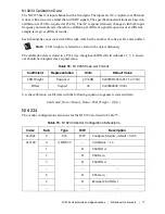
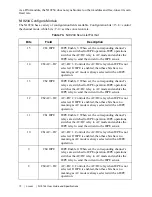
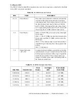
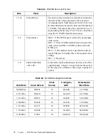
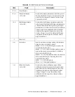
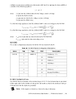
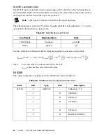
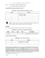
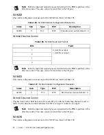
The vendor configuration extensions for the NI 9263 are listed in Table 92.
NI 9263 Calibration Data
The NI 9263 has four channels with a nominal range of ±10.7 V. Each channel has an associated
LSB weight, which is the number of volts per bit, and an offset, which is the number of volts per
bit measured when the inputs are grounded.
Note
LSB weight is referred to as Gain in the object dictionary.
Table 92.
NI 9263 Vendor Configuration Extensions
Index
Sub
Type
R/W
Description
0x2100
0
ARR:U32
—
Calibration = 16
1
R
Ch0 Offset
2
R
Ch0 Gain
3
R
Ch1 Offset
...
—
—
8
R
Ch3 Gain
9
R
External Ch0 Offset
...
—
—
y
mx b
–
=
Vcorrect
ed
Vraw bits
(
)
59605
nV
bits
---------
×
10
9
–
V
nV
-------
×
=
Vcorrect
ed
Vraw bits
(
)
118911
nV
bits
---------
×
10
9
–
V
nV
-------
×
=

