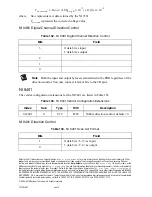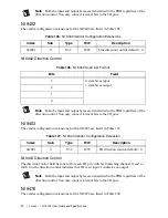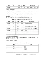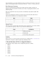
NI 9144 User Guide and Specifications
|
© National Instruments
|
79
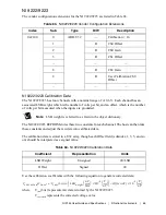
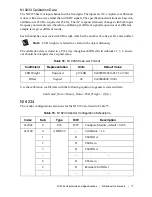
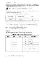
NI 9236 Calibration Data
The NI 9236 has eight input channels for measuring strain. Each channel has an associated LSB
weight, which is the number of volts per bit, and an offset, which is the number of volts per bit
measured when the inputs are grounded.
Note
LSB weight is referred to as Gain in the object dictionary.
There is also a shunt measurement value which is not used during normal operation. The
calibration data is stored in an U32 array, though each Offset field (subindex 1, 4, 7, etc) should
be interpreted as a signed value.
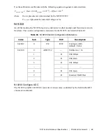
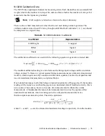
The calibration coefficients are used with the following equation to generate corrected data:
The resultant calibrated reading is a ratio between the bridge input voltage and the excitation
voltage, termed V
r
. However, typical quarter bridge measurements are ultimately denominated
in strain, which require not only conversion in the strain equation, but also the acquisition and
use of an unstrained measurement, as explained below.
Due to initial tolerances in all of the bridge elements (but primarily of the gage itself), the module
reading will be nonzero even when the gage is in an unstrained state. If handled correctly, this is
not a source of inaccuracy, however, because strain measurement is inherently a delta
measurement. A fundamental element of strain measurement involves the capture of this
unstrained measurement, which is analogous to the cold junction measurement of a
thermocouple measurement system. The strain equation is:
where
V
r –st
and
V
r –unst
are the strained and unstrained readings, respectively, from the module.
Table 84.
NI 9235 Calibration Coefficients
Coefficient
Representation
LSB Weight
Unsigned
Offset
Signed
Shunt
Signed
Nominal
V
V
---
Binary
Data
LSB
Weight
×
1
e
13
–
Offset
1
e
7
–
×
–
×
=
strain e
( )
4
–
V
r st
–
V
r unst
–
–
(
)
GF
1 2
+
(
)
V
r st
–
V
r unst
–
–
(
)
⋅
[
]
⋅
-----------------------------------------------------------------------------------
=

