background image

appears with an X and a reserved device appears as dark grey. Only one user at a time can
reserve the FieldDAQ device.

If the device was not reserved automatically after it was added (

Add Device

), you can reserve

the device in MAX by expanding 

Devices and Interfaces

»

Network Devices

, selecting the

device, and clicking the 

Reserve Network Device

 button. The Override Reservation dialog

box opens when you attempt to explicitly reserve a device. Agreeing to override the
reservation forces the FieldDAQ device to be reserved by the current user.

Verification

The following performance verification procedures describe the sequence of operation and test
points required to verify the FieldDAQ device. The verification procedures assume that
adequate traceable uncertainties are available for the calibration references. Complete the
following procedure to determine the As-Found status of the FieldDAQ device.
1.

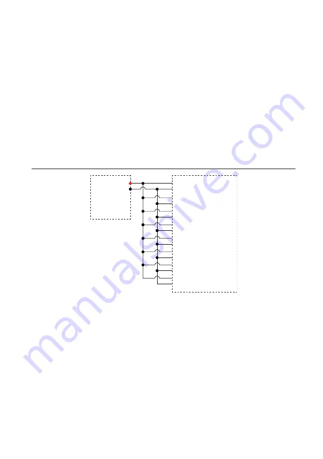
Connect the calibrator to Bank 1 of the FieldDAQ device, as shown in the following
figure.

Figure 1. Bank 1 Voltage Channel Verification Connections

TC0+

TC0–

HI

LO

TC1+

TC1–

TC6+

TC6–
TC7+

TC7–

Calibrator

FD-11613/11614

TC2+

TC2–
TC3+

TC3–
TC4+

TC4–
TC5+

TC5–

Bank 1

2.

On the calibrator, lock the voltage range to 3.3 V to reduce loading error.
a.

Set the output voltage to 2.0 V.

b.

Press the 3.3 V auto button to lock the 3.3 V range.

3.

Set the calibrator output to a Test Point value indicated in the following table.

4

  | 

ni.com

  | 

FD-11613/11614 Calibration Procedure

Summary of Contents for FD-11613

Page 1: ...to Go for Support 10 Software Requirements Calibrating the FD 11613 or FD 11614 requires the installation of NI DAQmx on the calibration system NI recommends using the latest NI DAQmx driver Earliest...

Page 2: ...pplications that use the NI DAQmx driver NI DAQmx C Reference Help Reference information for NI DAQmx C functions and NI DAQmx C properties Test Equipment The following table lists the equipment requi...

Page 3: ...rt Note You must install NI DAQmx 18 1 or later for device calibration support 2 Set up the FieldDAQ device as outlined in the FD 11613 11614 Quick Start 3 Configure the FieldDAQ device in Measurement...

Page 4: ...of operation and test points required to verify the FieldDAQ device The verification procedures assume that adequate traceable uncertainties are available for the calibration references Complete the...

Page 5: ...Accuracy Under Calibration Conditions 4 Set the calibrator to Operate mode OPR 5 Acquire and average samples a Create and configure an AI voltage channel on the FieldDAQ device according to the follow...

Page 6: ...om each channel and average the readings e Clear the task 13 Compare the average to the limits in the following table Table 6 FD 11613 11614 Voltage Verification Test Limits for Zero Test Points ADC T...

Page 7: ...eldDAQ device as shown in the following figure Figure 3 Bank 1 Voltage Channel Adjustment Connections TC0 TC0 HI LO TC1 TC1 TC6 TC6 TC7 TC7 Calibrator FD 11613 11614 TC2 TC2 TC3 TC3 TC4 TC4 TC5 TC5 Ba...

Page 8: ...gh g for each reference value in the array of adjustment points 4 Disconnect the calibrator from the FieldDAQ device 5 FD 11614 Connect the calibrator to Bank 2 of the FD 11614 as shown in the followi...

Page 9: ...onditions The values in the following table are based on calibrated scaling coefficients which are stored in the onboard EEPROM The following accuracy table is valid for calibration under the followin...

Page 10: ...d Logo Guidelines at ni com trademarks for information on NI trademarks Other product and company names mentioned herein are trademarks or trade names of their respective companies For patents coverin...

Reviews: