© National Instruments
|
2-1
2
Analog Input
To perform analog input measurements, insert a supported analog input C Series module into
any slot on the cDAQ controller. The measurement specifications, such as number of channels,
channel configuration, sample rate, and gain, are determined by the type of C Series module
used. For more information and wiring diagrams, refer to the documentation included with your
C Series modules.
The cDAQ controller has three AI timing engines, which means that three analog input tasks can
be running at a time on a controller. An analog input task can include channels from multiple
analog input modules. However, channels from a single module cannot be used in multiple tasks.
Multiple timing engines allow the cDAQ controller to run up to three analog input tasks
simultaneously, each using independent timing and triggering configurations. The three AI
timing engines are ai, te0, and te1.
Analog Input Triggering Signals
A trigger is a signal that causes an action, such as starting or stopping the acquisition of data.
When you configure a trigger, you must decide how you want to produce the trigger and the
action you want the trigger to cause. The cDAQ controller supports internal software triggering.
Three triggers are available: Start Trigger, Reference Trigger, and Pause Trigger. An analog or
digital trigger can initiate these three trigger actions. Up to two C Series parallel digital input
modules can be used in any controller slot to supply a digital trigger. To find your module
triggering options, refer to the documentation included with your C Series modules. For more
information about using digital modules for triggering, refer to Chapter 4,
.
Refer to the
, and
sections for more information about the analog input trigger signals.
Analog Input Timing Signals
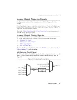
The cDAQ controller features the following analog input timing signals:
•
*
•
AI Sample Clock Timebase Signal
•


