NanoString Technologies nCounter User Manual Download Page 55


2017-07  MAN-C0034-06


|


55

NanoString Technologies

®


USER MANUAL

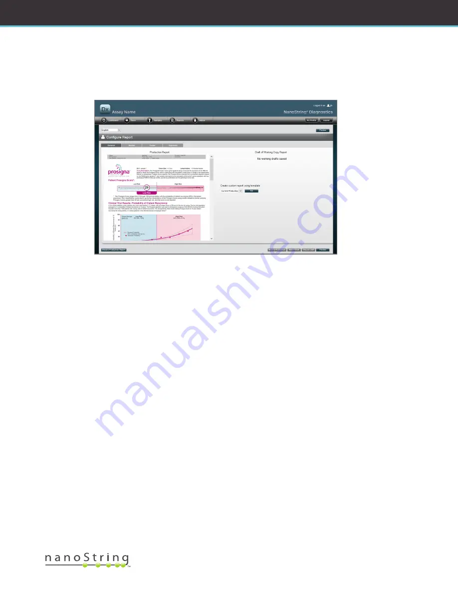
If there is no working draft in progress (See 

FIGURE 4.45

), then a dropdown listing of available templates is displayed instead of the thumbnail 

of the draft report, along with a control to start a new draft. Drafts may be started from the current production report, the NanoString 
standard header and footer, blank header and footer, or one of a number of pre-supplied templates. These templates are intended to be 
further modified by administrators to meet their organizations’ needs.

FIGURE 4.45: 

The 

General

 tab of the 

Configure Report

 page, displaying the menu for starting a new draft (Content of report varies 

by regulatory clearances or approvals)

Summary of Contents for nCounter

Page 1: ...tring com Phone 1 206 378 6266 1 888 358 NANO E mail dxsupport nanostring com For In Vitro Diagnostic Use The nCounter Dx Analysis System that is the subject of this manual is for use with NanoString s Diagnostic Assays within their intended use in the EU United States and other applicable markets 2017 07 MAN C0034 06 ...

Page 2: ...r hardware may be reproduced transmitted transcribed stored in a retrieval system or translated into other languages without the prior written consent of NanoString The manufacture use and or sale of NanoString product s may be subject to one or more patents or pending patent applications owned by NanoString or licensed to NanoString from Life Technologies Corporation and other third parties For a...

Page 3: ...Inc 530 Fairview Ave N Seattle WA 98109 USA Phone 1 888 358 NANO 1 888 358 6266 Fax 1 206 378 6288 E mail dxsupport nanostring com Website www nanostring com EU Authorized Representative Emergo Europe Prinsessegracht 20 2514 AP The Hague The Netherlands E mail dxsupport nanostring com Website www nanostring com ...

Page 4: ...entions 8 E Instrument Specifications 8 F Additional Precautions 9 G Caution Symbols 9 H Environmental Requirements 9 2 Hardware Overview 10 A General Information 10 B Prep Station 11 C Digital Analyzer 12 3 Selecting the Instrument Mode 13 A Prep Station 14 Select Instrument Mode 14 Switch Instrument Mode 16 B Digital Analyzer 17 Select Instrument Mode 17 Switch Instrument Mode 19 ...

Page 5: ...ables 25 Filter 25 Sort 27 Forms 28 C Dashboard and Status Pages 29 Dashboard 29 Run Set Status 30 Sample Status 32 D Run Sets 34 Create a Run Set 34 Edit a Run Set 38 Delete a Run Set 39 Editing Sample Information 39 E Print Worksheets 40 F Reports 41 G Administration 42 Add Delete and Manage Users 43 System Settings 47 Configure Report 53 Report Integration with External Systems 61 Editing Sampl...

Page 6: ...85 A Initiating a Run 85 7 Technical Support and Maintenance 90 A Technical Support 90 B Instrument Power Cycling 91 C Prep Station Maintenance 93 Electrode Alignment 93 O ring Lubrication 96 Downloading Log Files 99 Home Robot 99 D Digital Analyzer Maintenance 100 Downloading Log Files 100 E Cleaning Instructions 101 Prep Station 101 Digital Analyzer 101 F Disposal of Electronic Equipment 101 Sym...

Page 7: ...consists of two instruments the Prep Station and the Digital Analyzer A power cable is included with each instrument The Prep Station also includes a pipette tip rack a liquid waste container a solid waste container and silicone grease In addition to instrument software a web based software application web application is provided to configure runs to observe sample statuses and to download sample ...

Page 8: ...perlinks to online content or e mail addresses NOTE This symbol indicates general information that may be useful when performing assays These notes may clarify other instructions or provide guidance to improve the efficiency of the assay workflow IMPORTANT This symbol indicates important information that is critical when performing an assay CAUTION This symbol indicates the potential for bodily in...

Page 9: ...rd exists Ensure that all consumables are properly inserted into the system prior to starting a procedure Operate the system using only NanoString nCounter test kits in accordance with their Intended Use Wear gloves while operating or performing user maintenance on the instruments Do not attempt to wash the Prep Station s electrodes or allow water or other solvents to come into contact with the el...

Page 10: ...nformity EU only for compliance information Both instruments contain a touchscreen to enable operation of the instrument The touchscreen is a touch sensitive method of controlling the instrument that enables the user to operate the system by touching a selection on the screen Several buttons will appear in the touchscreen user interface such as Next Proceeds to the next screen Back Moves back to t...

Page 11: ...ly for use with NanoString nCounter Test Kits The instrument performs liquid transfers magnetic bead separations and immobilization of molecular labels on the Sample Cartridge surface FIGURE 2 1 FIGURE 2 1 The Prep Station The Prep Station deck must be loaded with the appropriate consumables prior to use FIGURE 2 2 FIGURE 2 2 The Prep Station Deck ...

Page 12: ...escannerconfiguredspecificallyforusewithNanoString snCounterTestKitCartridges Up to six Cartridges can be loaded into the instrument FIGURE 2 3 When one or more scans have been completed the instrument may be paused to allow new Cartridges to be swapped in without disrupting the remaining Cartridges FIGURE 2 3 The Digital Analyzer ...

Page 13: ...tructions provided in this chapter will not apply only the Diagnostics application mode will be available Proceed to Chapter 4 All NanoString IVD assays must be performed using the Diagnostics mode on these instruments In Diagnostics mode procedures and controls are in place to restrict access to data and some features to authorized users only For all other applications individuals using nCounter ...

Page 14: ...ft or Life Sciences mode green on the right FIGURE 3 1 The Prep Station Select Instrument Mode screen Touch the blue icon labeled NanoString Diagnostics to enter Diagnostics mode The system will load the application and present the Welcome screen FIGURE 3 2 Before operating the Prep Station a user must log on by selecting the Main Menu button FIGURE 3 2 The Welcome screen The Sign In screen will a...

Page 15: ...NanoString Technologies USER MANUAL Enter a valid user name and password and touch the Sign In button FIGURE 3 3 The sign in screen The Main Menu will appear FIGURE 3 4 FIGURE 3 4 The Prep Station Main Menu in Diagnostics mode ...

Page 16: ...de from the Main Menu Press the Exit button located at the bottom of the Main Menu FIGURE 3 4 The Exit Diagnostics Mode confirmation screen will appear FIGURE 3 5 The Prep Station Exit Diagnostics Mode confirmation screen Touch OK to exit Diagnostics mode and return to the Select Instrument Mode screen FIGURE 3 1 Touch Cancel to return to the Main Menu ...

Page 17: ... left or Life Sciences mode green on the right FIGURE 3 6 The Digital Analyzer Select Instrument Mode screen Touch the blue icon labeled NanoString Diagnostics to enter Diagnostics mode The system will load the application and present the Welcome screen FIGURE 3 7 Before operating the Digital Analyzer a user must log on by selecting the Main Menu button FIGURE 3 7 The Welcome screen The sign in sc...

Page 18: ... MANUAL nCounter Dx Analysis System Enter a valid user name and password and press the Sign In button FIGURE 3 8 The sign in screen The Main Menu will appear FIGURE 3 9 FIGURE 3 9 The Digital Analyzer Main Menu in Diagnostics mode ...

Page 19: ...om the Main Menu Press the Exit button located at the bottom of the Main Menu FIGURE 3 9 The Exit Diagnostics Mode confirmation screen will appear FIGURE 3 10 The Digital Analyzer Exit Diagnostics Mode confirmation screen Touch OK to exit Diagnostics mode and return to the Select Instrument Mode screen FIGURE 3 6 Touch Cancel to return to the Main Menu ...

Page 20: ...and edit Run Sets View the statuses of Run Sets Download reports Perform administrative functions A Sign In and Profile Management Sign In The local nCounter system administrator must provide each user with the URL to access the nCounter web application and will also set up the user account Navigate to the URL provided from any computer connected to the organization s local network It must be the ...

Page 21: ...ontrol will be displayed The user will then need to select an assay then click Continue FIGURE 4 2 FIGURE 4 2 The Assay Type control on the Sign In page Forgot User ID Password If you forget your user ID contact your local nCounter system administrator to retrieve it If the password is forgotten the nCounter web application may be able to retrieve it Click the link next to Forgot your password to ...

Page 22: ...system finds a matching profile the password will be e mailed to the address on record FIGURE 4 4 If a matching profile is not found you will be instructed to contact your nCounter system administrator in order to reset the password FIGURE 4 4 The confirmation page after a password has been requested ...

Page 23: ...Profile button The My Profile page enables the user to change the account password and or e mail address associated with the profile and view other account information FIGURE 4 6 See Section G Manage Users for more information about user types and privileges FIGURE 4 6 The My Profile page To accept any changes made to a profile click the Save button To discard any changes and return to the previou...

Page 24: ...s of recent activities Runs Create a Run Set and view run statuses a Run Set consists of 1 10 diagnostic samples and two mandatory reference samples processed at the same time Samples View sample statuses Reports Download reports Admin Manage users and other system settings FIGURE 4 7 The web application main menu Most of the menu options have sub menus that are available when a user hovers over t...

Page 25: ...ault reference samples are filtered out on the Samples page To turn filtering on click the symbol next to the Filter Settings header The header will expand and display available filter settings FIGURE 4 9 FIGURE 4 9 Filter settings are available when viewing most data NOTE Filtering is not available for the Manage Users page Filter the data using any of the fields in the table This will return any...

Page 26: ... or absence of a funnel icon next to the page title indicates whether or not filtering is applied FIGURE 4 11 An example of the funnel icon and filtered results on the Run Sets page Different filters are available depending on the page displayed For example the Samples page provides the ability to hide the two reference samples required for every run FIGURE 4 12 FIGURE 4 12 Check the Omit box to s...

Page 27: ...mn heading for the data of interest to sort the rows FIGURE 4 13 To re sort the data in the reverse order click again on the same column heading FIGURE 4 13 An example of alphabetically sorting samples by clicking on the SAMPLE ID column heading NOTE Tables are typically displayed by default with the most recently added items at the top and the oldest items at the bottom ...

Page 28: ...s Administrators may also access other forms which include Add New User Edit User Date and Time IP Address SSH Settings E mail Configuration All forms are designed with the expectation that users complete an action prior to moving to another area within the web application FIGURE 4 14 In order to navigate to another function after completing a form click Save to retain the information entered or C...

Page 29: ...nu option The Dashboard provides quick access to the statuses of Run Sets Samples and Reports assuming appropriate privileges have been applied to the user profile To view the complete status of any of these click on the Show All button on the right hand side of the title bar The Dashboard also provides quick access to common tasks located on the left side of the page Click on the appropriate link...

Page 30: ...n Set Status The Run Sets page can be accessed from the Dashboard as described above and is also available by clicking Runs on the menu bar The Run Sets page displays the statuses of all Run Sets that have been created FIGURE 4 16 FIGURE 4 16 Statuses of all Run Sets ...

Page 31: ...Batch Complete Run Set has completed processing ReportPending Report Pending scanning complete but waiting for the algorithm to complete ReportProcessing Report Processing algorithm is running but the report has not been produced yet ReportComplete Report Complete Digital Analyzer has finished scanning and reports are available for download from the Reports page ReportError Report Failed all proce...

Page 32: ... accessed from the Dashboard and is also available from the Samples menu option at the top of the page FIGURE 4 17 FIGURE 4 17 The location of the Samples menu option The Samples page allows users to view the statuses of all samples for all Run Sets FIGURE 4 18 FIGURE 4 18 The statuses of all samples contained within all Run Sets ...

Page 33: ...rred during processing on the Digital Analyzer ScanAbort DA Scan Abort manual abort on the Digital Analyzer ReportPending Report Pending Scanning complete but waiting for the algorithm to complete ReportProcessing Report Processing Algorithm is running but the report has not been produced yet ReportComplete Report Complete Digital Analyzer has finished scanning and reports are available for downlo...

Page 34: ...ocations using the nCounter web application A user can choose to create a new Run Set from several places within the web application The most common way is to select the option Runs from the menu bar at the top of the page and choose Create New Run Set from the sub menu that appears below FIGURE 4 19 FIGURE 4 19 The Create New Run Set option is available in the Runs sub menu The Create New Run Set...

Page 35: ...se between zero positive nodes 1 3 positive nodes or 4 positive nodes where available c Tumor Size required Users can choose between 2 cm or 2 cm d Memo optional Any notes about the sample can be entered here There is a maximum limit of 32 characters NOTE Leave the remaining fields blank if any strip tube wells are not needed If additional fields are required for more samples use a different test ...

Page 36: ...un Set when you have entered all information for the Run Set After you save the Run Set a prompt to print a worksheet will appear FIGURE 4 22 FIGURE 4 22 The Print Worksheet prompt Select OK to print the Run Set Worksheet NOTE Clicking the Cancel button will navigate the user to the Run Sets page NOTE The Run Set will still be saved in the application if a worksheet is not printed but it is recomm...

Page 37: ...tring Technologies USER MANUAL The worksheet will appear in a new window FIGURE 4 23 FIGURE 4 23 An example worksheet Select Print to print the worksheet and then close the worksheet The application will return to the Run Sets page ...

Page 38: ...rom the list on the Run Sets page and click the Edit button FIGURE 4 24 FIGURE 4 24 Location of the Edit button on the Run Sets page The Edit Run Set page will appear FIGURE 4 25 FIGURE 4 25 The Edit Run Set page NOTE Clicking on the Run Set ID hyperlink will NOT open the Run Set for editing Clicking the hyperlink will open the Samples status page pre filtered to view only that Run Set Verify that...

Page 39: ...ze were entered incorrectly These parameters may be changed in the Create Edit Run Set page before the sample is started on the Prep Station but after the sample has started on the Prep Station only an administrator can edit these fields and generate a new report This can only be done once per sample The new report will be marked as a revised report and for reference will include the obsolete para...

Page 40: ...ossible to print Run Set worksheets at any time from the nCounter web application To print a Run Set worksheet navigate to the Run Set page select the Run Set row of interest and click the Print Worksheet button FIGURE 4 28 FIGURE 4 28 Location of the Print Worksheet button on the Run Sets page The worksheet FIGURE 4 29 will appear in a new window FIGURE 4 29 An example worksheet Click the Print b...

Page 41: ... select the row s of samples to be downloaded and click the Download button FIGURE 4 30 If more than one language has been installed for an assay the Report Languages menu will be displayed in the upper left corner of the Report screen The user will need to select desired language s for downloaded reports before clicking on the Download button Language selections will be retained until the user mo...

Page 42: ... button is available in the top menu bar of the web application Administrators can choose these functions Manage Users System Settings Add User Configure Report In addition to the functions listed in the Admin menu two additional areas are restricted to Administrators LIS Integration Editing Sample Information ...

Page 43: ...dd Delete and Manage Users To add a new user select Admin from the top menu bar and click on Add User FIGURE 4 31 FIGURE 4 31 The location of the Add User button in the Admin sub menu The Add New User form will appear FIGURE 4 32 FIGURE 4 32 The Add New User form ...

Page 44: ... reports for the assay s selected Create Run Set This permission is required to create a new Run Set or edit an existing Run Set on the Web Application for the assay s selected NOTE Administrators do not automatically have permission to access diagnostic reports and initiate post hybridization processing on the Prep Station permission must still be assigned Administrators are able to assign permis...

Page 45: ...d user and click the Edit button The Edit User Data form will appear FIGURE 4 34 FIGURE 4 34 The Edit User Data form Edit any of the following information and click the Save button to save any changes made User ID Password Confirm Password E mail Address User Type Assay Permissions Run Post Hybridization Access Reports Create Run Set ...

Page 46: ... select the row for the appropriate user and click the Delete button FIGURE 4 35 FIGURE 4 35 Location of the Delete button on the Manage Users page A confirmation message will appear FIGURE 4 36 FIGURE 4 36 The Delete User prompt Click OK to delete the user or click Cancel to return to the Manage Users page ...

Page 47: ...rate tabs Date and Time default tab E mail Settings SSH Settings IP Address To access the System Settings page select the Admin option in the top menu bar and select the System Settings option FIGURE 4 37 FIGURE 4 37 Location of the System Settings option in the Admin sub menu The System Settings page will appear with the default Date and Time tab visible FIGURE 4 38 FIGURE 4 38 The Date and Time ...

Page 48: ...k Save to save any changes or Cancel to discard changes and perform another function NOTE Administrators cannot adjust the Time Zone or Daylight Saving Time options Contact NanoString Support if these values need to be adjusted NOTE Changing the date and or time in the nCounter web application adjusts these values on the Digital Analyzer and Prep Station as well Take care when making changes to th...

Page 49: ...secure e mail server required if Enable SSL is checked Password Password for SMTP username required if Enable SSL is checked Confirm Password Same password as above required if Enable SSL is checked Encryption Protocol These options effectively encrypt e mail data sent over the Internet between the client and e mail server The following are possible values for encryption protocol a selection is re...

Page 50: ...Name The name of the host used by the client for connecting to the SSH server SSH Port Number The port used by the client for connection to the SSH server SSH User Name SSH server account name used by the client for authenticating the connection Configurable fields Enable SSH Server Check box for enabling or disabling the SSH server Assay Backup Selection of assay report or system backup data to b...

Page 51: ...SER MANUAL Once the Enable SSH Server checkbox is enabled the Administrator can select which type of assay or backup data to configure for SSH access FIGURE 4 41 FIGURE 4 41 Assay Backup menu is active after the Enable SSH Server checkbox is selected ...

Page 52: ...ption allows the local network to automatically find and assign an IP address This address is subject to change IP Address IP address provided by the network administrator for Static IP address Subnet Subnet provided by the network administrator for Static IP address Gateway Gateway address provided by the network administrator for Static IP address DNS 1 Domain Name Server provided by the network...

Page 53: ...ther Personally Identifiable Information PII desired Users will need to save the completed forms outside the nCounter system as it is not currently engineered to support storage of PII The report body including assay results logos and explanatory graphs and text may not be modified Each installed localized assay is customized independently The administrator may only make changes to the assay selec...

Page 54: ... production and draft reports Discard Production Report Selecting this button will remove all user generated customization of the report and will revert to the default nCounter Dx Analysis System provided patient report Move to Production Move the current draft report to production This erases the current production report and cannot be undone Revert Draft Revert all parts of the draft report head...

Page 55: ...rt a new draft Drafts may be started from the current production report the NanoString standard header and footer blank header and footer or one of a number of pre supplied templates These templates are intended to be further modified by administrators to meet their organizations needs FIGURE 4 45 The General tab of the Configure Report page displaying the menu for starting a new draft Content of ...

Page 56: ... will be hidden by the body of the report and will not be visible The body of the report will begin immediately following the header unless the customized header explicitly includes blank lines there will be no visible gap between the user generated header content and the NanoString supplied body The Preview button may be used at any time to generate a PDF with the currently entered header fields ...

Page 57: ...ith the sample on the Create New Run Set page Remaining fields are assay specific parameters e g Tumor Size and Node Count Your specific assay may or may not have user entered parameters NOTE After initial placement images and tables may be further customized or refined by modifying certain properties These properties are accessed by right clicking control clicking on systems without a right mouse...

Page 58: ...ols available for the header are available for use in the footer area as well FIGURE 4 50 An example of the standard NanoString footer Signature Tab The Signature tab allows an administrator to optionally include a signature line on the last page of the report FIGURE 4 51 When the checkbox has been enabled the signature line can be edited and will be included on generated PDF files The editing too...

Page 59: ... For this example choose the Blank template then select Go 5 When the new draft is created select the Header tab to edit the header 6 Click in the content area to start editing 7 Select the table tool to create a new table 8 In the Insert Table dialog choose the following then select OK when all parameters are entered a 5 columns b 5 rows c Width Custom 90 d Border color 4th entry in the 3rd row 3...

Page 60: ...l of the third column then select Add Run Set ID Field from the menu 24 Click in the fourth cell of the third column then select Add Run Date Field from the menu 25 Click in the last cell of the third column then select Add Comments from the menu 26 Right click in the last cell of the third column then select Merge Right Repeat so that the cell spans the remainder of the table 27 Click in the firs...

Page 61: ...the SSH server the assay specific files are arranged as follows Assay directory Description and contents login directory Top level directory contains XML export files and all subdirectories listed below pdf PDF files For each completed sample the NanoString standard report will always be present if a customized report has been defined the PDF of that report will also be in this directory image Org...

Page 62: ...p zXX Encrypted ZIP archive of backup data XX represents a number Image filenames have an additional component appended after the basename portion This component serves to identify the precise contents of the file Elements listed in square brackets are optional and may not exist for all reports The additional elements for image files are Component Contents _head Header _body Body content indicates...

Page 63: ...te a new report This can only be done once per sample The new report will be marked as a revised report and for reference will include the obsolete parameters and results In addition if the Prep Station or Digital Analyzer has been initiated prior to realizing the parameters were entered incorrectly do not abort the run but allow it to fully complete and then edit the sample parameters for the rev...

Page 64: ... sample parameter fields of Positive Nodes and Tumor Size in this example and Memo for adding comments if desired can be revised Use the input controls to revise one or more fields After the field has been revised the Justification text box will be active The administrator must enter a justification in order to revise the sample IMPORTANT Note the warning on this screen ...

Page 65: ...alyzer A revised report will be generated based on the updated parameters The revised report will be marked as such and will also include the original obsolete parameters and results When the revised report has been generated it will replace the original report on the Report download page Revised reports are indicated by a after the Sample ID FIGURE 4 56 The original report will be retained on the...

Page 66: ...must first configure the Backup Data aspect of nCounter SSH Server functionality see FIGURE 4 41 Note The SSH Backup Data option is a separate feature from the SSH Assay Data feature Assay reports which are also available via the nCounter SSH server do not contain system backup data To access the backup archive IT administrators will need to use their SSH client of preference 1 Log into the Dx sys...

Page 67: ...he combined receptacle by using the latch on the front and dispose of the liquid appropriately Tips should be discarded into the appropriate waste receptacle as outlined in the local organization s laboratory procedures If biohazardous samples are not being used in the system and if permitted by the laboratory procedures liquid waste may be disposed of in the sink or other drain 3 Verify that the ...

Page 68: ...lcome screen on the Prep Station touchscreen 1 To process samples using the Prep Station a user must log on to the instrument In order to log on touch Main Menu on the Welcome Screen FIGURE 5 1 The Prep Station Welcome screen 2 Enter a valid user name and password and touch Sign In FIGURE 5 2 The sign in screen The Main Menu will appear FIGURE 5 3 ...

Page 69: ...nu The Process A Run Set screen will appear FIGURE 5 4 The Process A Run Set screen displays the name of each Run Set the assay type and the number of samples it contains NOTE The Exit button will only appear on the Welcome screen and Main Menu if the user has the nCounter Dx Analysis System with FLEX configuration see Chapter 3 Selecting the Instrument Mode ...

Page 70: ... Review Reaction Layout screen with two reference samples yellow and 10 patient samples blue One patient sample is selected green 5 Touch individual samples to view their details Verify that the Run Set and sample information are correct FIGURE 5 5 If not return to the web application and make the appropriate corrections First touch Cancel on the Prep Station to make them available for editing If ...

Page 71: ... web application FIGURE 4 19 The Reagents And Cartridge screen will appear FIGURE 5 7 The Reagents And Cartridge screen 7 Cartridges and Reagent Plate s FIGURE 5 8 must be at room temperature prior to processing a Remove the nCounter Reagent Plates from storage at 4 C and the nCounter Cartridges from storage at 20 C Allow them to equilibrate to room temperature for 10 15 minutes FIGURE 5 8 A seale...

Page 72: ...s onto the Prep Station deck c While the Cartridges and Reagent Plates come to room temperature continue setting up the Prep Station Touch Next The Waste Receptacles screen will appear FIGURE 5 9 The Waste Receptacles screen 8 Make sure the disposables from the previous run have been appropriately discarded Press Next The Scan Reagent Plate screen will appear FIGURE 5 10 The Scan Reagent Plate scr...

Page 73: ...nt Plates on the deck as indicated on the screen FIGURE 5 10 The deck has alignment pins that will allow the Reagent Plates to sit flat only if they are in the correct orientation The Reagent Plate should be oriented with the barcode facing the user FIGURE 5 11 If the Reagent Plate is placed in the wrong direction the Prep Station will pause the protocol at the validation step until the user inter...

Page 74: ... the foil piercers into the carrier Hold the plastic tip rack by the center tabs hold the tip rack over the metal holder and slowly lower the tips into the metal holder It is helpful to place the carrier at eye level to align the plastic tips FIGURE 5 13 FIGURE 5 13 Insert the tips and foil piercers into metal tip carrier NOTE Each box contains two nested sets of tips each side of the box contains...

Page 75: ...e deck FIGURE 5 14 FIGURE 5 14 Proper placement of rack containing pipette tips and foil piercers d Touch Next The Tip Sheaths screen will appear FIGURE 5 15 FIGURE 5 15 The Tip Sheaths screen NOTE Tip sheaths are used to reduce the amount of consumable waste They allow the system to dedicate tips to a set of 6 samples and store them while the other 6 samples are being processed ...

Page 76: ...pty Strip Tubes screen 12 Place the empty strip tubes in the heater on the deck Touch Next The Scan Sample Cartridge screen will appear NOTE Only one empty heater strip tube is required for runs performed using a 1 2 3 or 4 test kit For these Run Sets load the empty heater strip tube into the front position of the heat block nearest the user on the Prep Station deck FIGURE 5 17 The Scan Sample Car...

Page 77: ...r the barcode for the Cartridge If a barcode will not scan or is not accepted use another Cartridge from the same kit lot for the run b Insert a Sample Cartridge under the electrode fixture in the orientation shown in FIGURE 5 18 Place the Cartridge on the deck and slide it into position avoiding the electrodes Make sure that it is seated completely in the machined depression When positioned prope...

Page 78: ...le to lower the fixture Doing so will prevent the fixture from locking Instead press on the body of the fixture away from the release handle FIGURE 5 20 IMPORTANT IIf any resistance is felt while lowering the fixture stop and adjust the position of the Cartridge slightly Make sure that the electrodes are correctly aligned If the electrodes are not aligned re align the electrodes using the Align El...

Page 79: ... orientation guides IMPORTANT Do not let the hybridized samples sit at room temperature longer than 15 minutes If there are delays between removing the hybridized samples from the heat block and starting the Prep Station return the samples to 65 C until they can be processed Do not exceed the maximum hybridization time stated in the assay package insert IMPORTANT All tubes should be seated fully a...

Page 80: ...r the tubes FIGURE 5 23 FIGURE 5 23 Lid closed over tubes b Touch Next IMPORTANT Failure to securely close the lid over the tubes can result in a system malfunction If the metal lid is not closed completely then the sensor will return an error message and the run will not initiate until the error is corrected ...

Page 81: ...will appear FIGURE 5 24 FIGURE 5 24 The Notification Options screen 16 Select whether the Prep Station should make an audible alarm when processing is finished Touch Next The Start Deck Validation screen will appear FIGURE 5 25 The Start Deck Validation screen a Touch Next to begin validation ...

Page 82: ...eration If the Prep Station determines that a consumable is misplaced it will instruct the user to fix the configuration FIGURE 5 26 The Post Hybridization Validating Deck Layout screen c After deck validation is complete FIGURE 5 27 a new screen containing the Start Processing button will appear Touch Start Processing to initiate the run FIGURE 5 27 The Post Hybridization Deck Layout Validated sc...

Page 83: ... run was completed FIGURE 5 28 Touch Next FIGURE 5 28 The System Processing Complete screen 18 The Run Successfully Completed screen lists the steps to follow after sample processing including a Remove and discard empty Reagent Plates b Remove and discard the empty tip racks and foil piercers c Remove and discard all strip tubes d Remove the Sample Cartridge and seal the wells ...

Page 84: ...0 After processing is complete it is important to do the following a Seal the wells immediately with the adhesive cover provided to prevent evaporation b Protect Samples from as much light as possible c If the Cartridge will not be scanned on the Digital Analyzer within an hour the sealed Cartridge should be stored at 4 C in an opaque box The Cartridge can be stored this way for up to one week wit...

Page 85: ...yzer A Initiating a Run 1 To scan a Cartridge using the Digital Analyzer log on to the instrument In order to log on touch Main Menu on the Welcome screen FIGURE 6 1 The Digital Analyzer Welcome screen 2 Enter a valid user name and password and touch Sign In FIGURE 6 2 The sign in screen ...

Page 86: ...r on the Welcome screen and Main Menu if the user has the nCounter Dx Analysis System with FLEX configuration see Chapter 3 Selecting the Instrument Mode IMPORTANT If a laboratory has more than one Digital Analyzer the Cartridge must be scanned on the same instrument registered to the Prep Station used to process the samples see Chapter 4 Operating the Web Application ...

Page 87: ... and close the door to the Digital Analyzer FIGURE 6 4 Orient Cartridges with the barcode toward the user when placing them into the Digital Analyzer Close the magnetic clips gently and be sure to push down on the metal plate above the Cartridge after the lid is closed to ensure the Cartridge lays flat a Select the Start Counting button The Checking Stage Configuration screen will appear FIGURE 6 ...

Page 88: ...nning of that Cartridge is complete Icon and text over a Cartridge There may have been a problem encountered during a scan of the Cartridge Touch the icon or Cartridge to get more information In the example shown in FIGURE 6 6 the Cartridge in slot 1 is being scanned and Cartridges in slots 2 3 4 5 and 6 are waiting to be scanned FIGURE 6 6 The Counting Cartridge screen with the current cartridge ...

Page 89: ...ould re lock and resume counting FIGURE 6 7 The Pause Counting Job screen 7 When a Cartridge is finished scanning an e mail notification will be sent to the user and the processing screen will change to reflect that the Cartridge has completed FIGURE 6 8 Upon receiving the e mail notification that the scan has completed remove the completed Cartridge In case of an instrument error or reports not b...

Page 90: ...rt is available by phone fax mail or e mail Please be sure to include the product number and serial number in all communications U S Contact Information NanoString Technologies Inc 530 Fairview Ave N Seattle WA 98109 U S A Phone 1 888 358 NANO 1 888 358 6266 Fax 1 206 378 6288 E mail dxsupport nanostring com Website www nanostring com ...

Page 91: ...Users must be assigned Administrator privileges by an Administrator to perform these functions Only Administrators may shut down the system NOTE Shutting down the IVD system will interrupt Cartridge preparation and analysis Please ensure that all Cartridges have finished processing on the Digital Analyzer and the Prep Station is not in use before cycling instrument system power The following instr...

Page 92: ...nds locate the power switch on the back of the instrument and turn off the power 4 Wait an additional 30 seconds and then use the power switch to restore power to the instrument The system will initialize and display the Select Instrument Mode screen see Chapter 3 Selecting the Instrument Mode IMPORTANT To ensure proper communication between instruments after a power cycle always restore power to ...

Page 93: ...artridge and bend The following describes a method for re alignment of the electrodes using the system hardware interface This method allows the electrode fixture to tilt at an angle that makes it much easier to view the electrodes during alignment If the electrode is so severely bent that it cannot be inserted into a Cartridge the process outlined below may need to be repeated twice once without ...

Page 94: ...ghtly bent and a Cartridge can be inserted by carefully maneuvering the bent electrode then insert a Cartridge before closing the electrode fixture Touch Next The Align Electrodes Close Door screen will appear FIGURE 7 5 The Align Electrodes Close Door screen step 2 of 5 3 Close the door and touch Next While the door is closed the electrode fixture tilts towards the operator for easier access to t...

Page 95: ...gn the tip of the electrode to the center and bottom of the Cartridge well Touch Next The final screen will appear when the procedure is complete FIGURE 7 7 The Align Electrodes Close Door screen step 5 of 5 5 Close the door and touch Finish The electrode fixture will tilt back to its home position and then the Maintenance Menu will be displayed ...

Page 96: ...litate O ring lubrication by bringing the pipetting head to the front of the deck for easy access NOTE An icon will appear on the Main Menu and Maintenance Menu when it is necessary to lubricate the O rings FIGURE 7 8 FIGURE 7 8 The yellow Lubricate O rings symbol CAUTION When performing maintenance functions always use appropriate safety precautions including wearing safety glasses and gloves Som...

Page 97: ...tring Technologies USER MANUAL 1 Select Lubricate O Rings on the Maintenance Menu A series of Lubricate O rings maintenance screens will appear FIGURE 7 9 Screens displayed for the different steps in the Lubricate O rings workflow ...

Page 98: ...he O rings 4 Using lint free paper thoroughly wipe off any excess silicone grease from the nozzles and Tip Ejectors 5 Gently move that finger around each ring to distribute the grease evenly 6 Following the instructions on the screen touch the Next and Finish buttons to complete the procedure 7 Completing the Lubricate O rings workflow will reset the internal timer and remove the yellow warning ic...

Page 99: ...ted for download by touching each one Selected folders will be highlighted in blue 1 Insert a USB flash drive into the Prep Station s front USB port 2 When the desired folders have been selected touch Download to transfer them to the flash drive FIGURE 7 11 Screens that appear when downloading log files Home Robot If the robot enters into an undesirable state selecting the Home Robot button can ho...

Page 100: ...r has been designed to require no maintenance by the user other than instrument power cycling see previous section However if any issues occur NanoString Support may request a download of the log files Downloading Log Files In the Maintenance Menu select the Download Logs button Log files are stored according to the date of each run Multiple dated folders may be selected for download by touching e...

Page 101: ...irectly on the instrument Digital Analyzer Clean the exterior periodically using a diluted neutral soap followed by water Use a damp towel rather than spraying directly on the instrument F Disposal of Electronic Equipment IMPORTANT This symbol on the nCounter Dx Analysis System is required in accordance with the Waste Electrical and Electronic Equipment WEEE Directive of the European Union The pre...

Page 102: ...lt Instructions for Use CE Mark Catalogue or Reference Number Batch code Lot number Serial number Contains sufficient for n tests Temperature range storage conditions Lower limit of temperature storage conditions Upper limit of temperature storage conditions For Use by Expiry Date Date of manufacture Room Temp Room Temperature HYB Hybridization Regulatory Disclaimer For in vitro diagnostic use ...

Page 103: ...Ave N Seattle Washington 98109 USA CONTACT US info nanostring com Tel 1 888 358 6266 Fax 1 206 378 6288 www nanostring com INFORMATION United States us sales nanostring com Europe europe sales nanostring com Other Regions info nanostring com 2013 2017 NanoString Technologies Inc All rights reserved ...

Reviews: