


Page 12
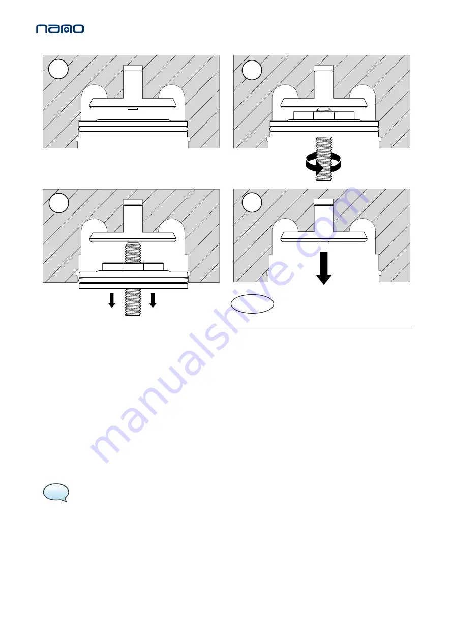
5. Remove the valve seat by inserting the valve extraction tool through the middle of the seat valve, resting the narrow
end of the tool on the dome point of the check valve.
6. Rotate the thread of the tool, moving the plate attached to it and forcing the check vale out of the valve orifice
within the outlet manifold.
7. Once the valve seat is removed, remove the check valve by hand.
8. Remove the DU bush and replace it from the NVK-CHK service kit.
9. Replace the check valve firstly from the service kit, then secondly replace valve seat.
10. Replace the circlip from the service kit.
11. Replace he seal between the dryer column and top manifold.
12. Place the manifold back on top of the dryer column and insert the 8x M12 cap head screws and 8x washers and
tighten at a torque setting of 80Nm.
NOTE:
Refer to
CH. 14. MANIFOLD TIGHTENING SEQUENCES
and follow the correct tightening sequence.
13. Replace the top cover and insert the 4x M5 screws to secure it in place. Hand tighten these screws only or tighten
to a torque setting of less than 1Nm
.
When service B is complete reset the dryer, Refer to:
1
2
3
4
Figure 2.
CH. 13. RESETTING DRYER CONTROLLER


