Page-2
2. Basic specifications
2.1 ES06-01 basic specification
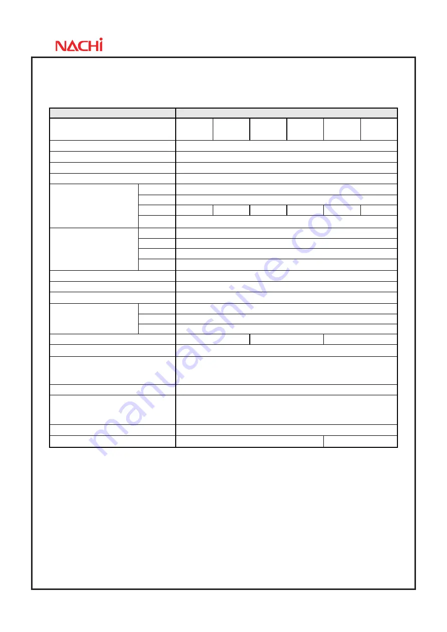
Item
Specifications
Robot model
ES06
-3520-01
ES06
-3534-01
ES06
-4520-01
ES06
-4534-01
ES06
-5520-01
ES06
-5534-01
Construction Horizontally
Articulated
Number of axis
4
Drive system
AC servo motor
Brake
Axis 1, 2 and 4 ; without brake Axis 3 ; with brake
Axis 1
±2.97 rad
(
±170 °
)
Axis 2
±2.53 rad
(
±145 °
)
Axis 3
200 mm
340 mm
200 mm
340 mm
200 mm
340 mm
Max. working envelope
Axis 4
±6.28 rad
(
±360 °
)
Axis 1
6.98 rad/s
(
400 °/s
)
Axis 2
11.69 rad/s
(
670 °/s
)
Axis 3
2400 mm/s
Max. speed
*4
Axis 4
43.63 rad/s
(
2500 °/s
)
Rated pay load (maximum)
3 kg ( 6 kg )
Maximum pushing down force of axis 3
*7
165
N
Allowable moment of inertia
*1
0.12 kg
・
m
2
(rated 0.01 kg
・
m
2
)
X-Y plane
±0.012 mm
J3 (Z)
±0.01 mm
Position repeatability
J4 (
θ
)
±0.004 °
Longest reach
350 mm
450 mm
550 mm
Air tubes
Primary
:φ
6×2 Secondary
:φ
4×8
*5
Application signals
Gripper 8 input / 8 output (20 core)
Specified wires for multi purpose gripper (2core + power 2core)
Ethernet cable ×1 <100BASE-TX> (8core)
*6
Installation Floor
mounting
Ambient conditions
Temperature: 0 to 40 ºC
*2
Humidity: 45 to 85%RH (No dew condensation allowed)
Vibration to the installation face: Not more than 0.5G (4.9 m/s
2
)
Environmental performance
*3
IP20
Robot mass
36 kg
37 kg
1[rad] = 180/π[°], 1[N
・
m] = 1/9.8[kgf
・
m]
- On controller display, axis 1 to 4 is displayed as J1 to J4 for each.
- The specification and externals described in this specification might change without a previous notice for the improvement.
- The explosion proof specification is not available.
*1: The Allowable moment of inertia of a wrist changes with load conditions of a wrist. *2: Permitted height is not higher than
1,000m above sea level. If used in higher place, permitted temperature is affected by height. *3: Liquid such as organic
compound, acidity, alkalinity, chlorine or gasoline cutting fluid which deteriorates the seal material are not available to use. *4:
The "Max. speed" in this table is the available maximum value and will change depending on the work-program and the wrist
load condition. *5: Secondary tube
φ
4 is a set of solenoid valve option. *6: LAN cable (8core) can be used for auxiliary
wires. *7: This is a maximum pushing down force at tool top point when maximum payload is mounted and axis 1, 2 and 4
does not move. Please use robot under specified limit. In case that continuous pushing down force is applied, overload error
may occur. Please use robot under the condition of which no overload error occurs.


