Page-20
8. Application wires and tubes diagram
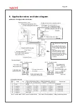
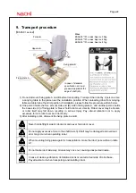
■ Exterior of Gripper wires and tubes
Connector and joint
Robot side (accessory of robot)
Opposite (prepared by customer)
Parts
No.
Name Q’ty
Connector, Joint
Connector pin
Connector
Connector pin
Manufacturer
(1) Joint
2 UKBL6
-
-
-
KOGANEI
(2) Connector
2 1-1717834-4 1318108-1 1-1318115-4
1318112-1 TE
connectivity
(3) Connector
2 1-1717834-3 1318108-1 1-1318115-3
1318112-1 TE
connectivity
(4) Connector
1 1-1318117-3 1318112-1 1-1318120-3
1318108-1 TE
connectivity
(5) Connector
1 2-1717834-4 1318108-1 2-1318115-4
1318112-1 TE
connectivity
(6) Connector
1 TM21P-88P
-
-
-
Note1) 1 for ES06 series, 2 for ES12 series of Clean specification, 1 for all model of Oil mist specification, Nothing for standard specification.
1
次配管エアホース
(AIR OUT
、
RETURN)
(4)
ハンド入力信号コネクタ
(HC1
、
2)
(3)
ハンド出力信号コネクタ
(GR1
、
2)
2
次配管エアホース
(
オプション、もしくはお客様ご準備
)
RH-6FH
シリーズ:
φ
4
ホース
(
最大
8
本
)
RH-12FH/20FH
シリーズ:
φ
6
ホース
(
最大
8
本
)
電磁弁セット
(
オプション
)
(3)
ハンド出力信号コネクタ
(GR1
、
2)
(
ロボット本体側
)
1
次配管エアホース
(AIR OUT
、
RETURN)
(
ロボット本体側
)
A
視
第
1
アーム
第
2
アーム
ベース
(6)
多機能ハンド専用信号線
(2
芯
+
電源線
2
芯
)
(7)
イーサネットケーブル
(8
芯
)
※
LAN
コネクタを切断し、お客様ご準備
のコネクタを接続してイーサネット以外
の用途にもご利用できます。
(5)
予備線
(2
芯
)
B
配線・配管の引き出し
配線・配管は、シャフト内を通すこと
ができます。
また、
「外部配線配管ボックス
(
オプシ
ョン
)
」
を使って第
2
アーム後部から外
部へ引き出すこともできます。
ベース部は、後部のグロメットからイー
サネットケーブル、リモート入出力用
電源線を引き出すことができます。
注)
クリーン仕様、ミスト仕様では、
ケーブル引出口を封止する必要
があります。
ロボット本体背面図:
B
<CR750
コントローラ接続
>
<CR751
コントローラ接続
>
(1) 1
次配管エア継手
(
φ
6)
(
AIR IN
、
RETURN
)
イーサネットケーブル、多機能ハンド
専用電源線引出口
(
グロメット
)
機器間ケーブル
(
電源用
)
コネクタ
(CN1)
機器間ケーブル
(
信号用
)
コネクタ
(CN2)
機器間ケーブル
(
信号用
)
コネクタ
(CN2)
(
カバーの内側
)
機器間ケーブル
(
電源用
)
コネクタ
(AMP1
・
AMP2)
(
カバーの内側
)
(
カバーの内側
)
機器間ケーブル
(
ブレーキ用
)
コネクタ
(BRK)
A
(1)
(2)
(2)
(3)
(4)
(5)
(6)
Primary air horse (air out, return)
(3) Gripper input signal connector (HC1,2)
(3) Gripper output signal connector (GR1,2)
Secondary air horse (option or prepared by customer)
RH-6FH series :
φ
4 horse (8 at maximum)
RH-12FH/20FH series :
φ
6 horse (8 at maximum)
Solenoid valve set (option)
(2) Gripper output signal connector (GR1,2)
(Robot side)
Primary air horse (air out, return)
(Robot side)
Upper arm
Base
(5) Signals for Multi function gripper
(2 core + 2 power)
(6) Ethernet cable (8 cores)
(4) Aux. wires (2 cores)
(Free to utilize for another purpose by
cutting off LAN connector)
Fore arm
View from A
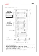
Robot back side view; B
Controller connection
Controller connection
Wires and tubes can be through inside
shaft.
Also by utilizing “External wires and
tubes box” option, those are able to go
out from robot body from backside of
fore arm.
Ethernet cable and power cable for
remote I/O are able to go out from
grommet of rear panel at robot base.
Notes) Cable outlet must be covered for
clean specification and oil mist
specification.
(1) Primary air tube joint (
φ
6)
(air in, return)
Cables between units
(power) connector CN1
Cables between units
(signal) connector CN2
Ethernet cable, Signals for Multi
function gripper Outlet (grommet)
Cables between units
(power) connector AMP1, AMP2
Cables between units
(signal) connector CN2
(inside cover)
Cables between units
(brake) connector BRK
(inside cover)
(inside cover)


