background image

73 


115895B System Installation Manual 


MODBUS TCP & SNMP COMMUNICATION OPTION SECTION 


SECTION 2 


Description of Operation 


The single-phase Illuminator Supernova Emergency Lighting Central 

Inverter acts as a MODBUS TCP server, and SNMP Agent (server).  

 
It supports a total of 

nine

 analog objects (sixteen-bit integers), and 

seventeen

 binary flag objects. 

 
It can also be programmed to transmit SNMP 

‘traps’ when a programmed 

condition is met (analog value goes above or below a threshold value, or binary 
flag gets set to 1 or cleared to 0). The traps can be sent to specified IP 
addresses on the LAN. 


SECTION 3 


Default Ethernet Settings 


IP Address:

 10.0.0.101  (static) 


Subnet Mask: 

255.255.255.0 


Gateway:

 10.0.0.1 


DHCP Client:

 Turned off by default (but DHCP is supported) 


Web Server Port:

 80 (HTTP default) 


Default MODBUS TCP Settings 


Port

: 502 


Default SNMP Settings 


SNMP Version Support

: v1, v2c          (v3 is 

not

 supported) 


Community

: public 


Traps

: Disabled


Summary of Contents for Illuminator Supernova Series

Page 1: ... Installation Manual Illuminator System Series Supernova 1 75 kW 16 7 kW Installation Guide 44 South Commerce Way Bethlehem PA 18017 1 800 526 5088 610 868 3500 Fax 610 868 8686 Service 610 868 5400 www myerseps com ...

Page 2: ... type batteries contain either acid or alkali and can cause burns to skin and eyes If battery fluid is spilled on skin or in the eyes flush with fresh water and contact a physician immediately 5 Equipment should be mounted in locations where unauthorized personnel will not readily subject it to tampering 6 The use of accessory equipment not recommended by Manufacturer may cause an unsafe condition...

Page 3: ...NTIRE MANUAL AND REVIEW ALL DOCUMENTATION BEFORE ATTEMPTING SYSTEM INSTALLATION FOR SERVICE OR INSTALLATION INFORMATION TELEPHONE 610 868 5400 24 HR HOTLINE FAX 610 954 8227 FOR YOUR PROTECTION PLEASE COMPLETE AND RETURN WARRANTY REGISTRATION CARD IMMEDIATELY ...

Page 4: ...UNICATION OPTION MANUAL 31 SECTION 2 BACNET IP SNMP COMMUNICATION OPTION MANUAL 37 SECTION 3 MODBUS SERIAL COMMUNICATION OPTION MANUAL 54 SECTION 3 MODBUS TCP SNMP COMMUNICATION OPTION MANUAL 70 SECTION 4 RS 232 COMMUNICATIONS MANUAL 83 SECTION 5 SERIAL TO ETHERNET ADAPTER QUICK START MANUAL 98 SECTION 6 SYSTEM OPTIONS MANUAL BATTERY THERMAL RUNAWAY 103 PART 3 DRAWINGS 113 BATTERY INTERCONNECT 114...

Page 5: ...ARTS inside the system WARNING Do not install the system outdoors Do not install near gas or electric heaters or in other high temperature locations Use caution when servicing batteries Battery acid can cause burns to skin and eyes If acid is spilled on skin or in the eyes flush with fresh water and contact a physician immediately Equipment should be mounted in locations where unauthorized personn...

Page 6: ...qualified service personnel such as a licensed electrician should perform the system and battery installation and initial startup There is a risk of electrical shock Please record your unit s part number serial number and model number below You can find these numbers on the labels on the inside of the system s right door Part Number __________________________ Serial Number ________________________...

Page 7: ...6 115895B System Installation Manual Unit 1 1 75 5 0kVA Unit 3 10 0 16 7kVA Unit 2 6 25 7 5kVA C H A P T E R 3 BEFORE INSTALLING THE UNIT Installation Dimensions and Clearances ...

Page 8: ... 25 53 36 50 5 128 3 cm 34 18 2 06 2 38 3 38 63 5 cm 135 9 cm 91 4 cm 86 8 cm 5 2 cm 6 0 cm 8 6 cm Extended Height 61 58 5 Option 155 cm 148 5 cm Unit 3 10 0 16 7KVA Unit Depth A Height B Width C D E F G H Cabinet 25 78 3 42 71 38 181 3 cm 38 88 6 38 19 5 4 5 63 5 cm 199 cm 106 7 cm 98 8 cm 16 2 cm 49 5 cm 11 4 cm Table 3 2 Required Clearances Sides Top Front 0 0 0 cm 12 30 5 cm 39 100 0 cm Table ...

Page 9: ...els 1 75kw 2 5kw 3 75kw 5 0kw 6 25kw 7 5kw 10 0kw 12 5kw 16 7kw Unit with Standard SLC Batteries 620 785 1029 1273 1664 1908 2495 3470 3471 Unit without Batteries 297 297 297 297 444 444 1031 1031 1031 Table 3 5 System Weight in lbs kg for 120 Minute System Models 120 Minute System Models 1 31kw 1 88kw 2 81kw 3 75kw 4 69kw 5 63kw 7 5kw 9 38kw 12 5kw Unit with Standard SLC Batteries 620 785 1029 12...

Page 10: ... conditions can make the temperature within battery strings vary which can cause differences in the batteries voltages Eventually these conditions affect battery performance Do not allow tobacco smoking sparks or flames in the system location because hydrogen is concentrated under the vent cap of each cell of the battery Hydrogen is highly explosive and it is hard to detect because it is colorless...

Page 11: ...andard 1 75 kW 2 5 kW 3 75 kW 5 0 kW 6 25 kW 7 5 kW 10 0 kW 12 5 kW and 16 7 kW models do not have external battery cabinets Figure 4 1 Typical Hardwired Installation To Supported Loads Building Service Panel To Supported Loads Building Service Panel To Supported Loads Building Service Panel 10 0 16 7kVA 1 75 5 0kVA 6 25 7 5kVA ...

Page 12: ...ore installing the AC wiring Always wear protective clothing and eye protection and use insulated tools when working near batteries Whenever you are servicing an energized unit with the inside panel open electric shock is possible follow all local safety codes TEST BEFORE TOUCHING To reduce the risk of fire or electric shock install the unit and its batteries in a temperature and humidity controll...

Page 13: ... 80A 6 25 kW 208V 41 amps 50A 6 25 kW 240V 35 amps 40A 6 25 kW 277V 31 amps 35A 6 25 kW 480V 18 amps 25A 7 5 kW 120V 84 amps 100A 7 5 kW 208V 49 amps 60A 7 5 kW 240V 42 amps 50A 7 5 kW 277V 37 amps 45A 7 5 kW 480V 21 amps 25A 10 0 kW 120V 113 amps 150A 10 0 kW 208V 65 amps 80A 10 0 kW 240V 56 amps 70A 10 0 kW 277V 49 amps 60A 10 0 kW 480V 28 amps 35A 12 5 kW 120V 141 amps 175A 12 5 kW 208V 81 amps...

Page 14: ... disconnecting AC to the unit Only authorized persons shall be able to disconnect AC to the unit see NEC 700 20 and 700 21 If you are using the input circuit breaker to disconnect AC you must make sure that only authorized persons have control of the circuit breaker panel to meet the requirements of NEC 700 20 8 Read the following caution before removing conduit knockouts CAUTION To prevent electr...

Page 15: ...ERNAL MAINTENANCE BYPASS IS REQUIRED SEE DEVIATION DRAWING FOR WIRING OF LOAD OUTPUT 12 Connecting load wires without system distribution circuit breakers connect load wires to the system s terminal block labeled OUTPUT Connect hot wire s to the output block marked Nor On the common wire s to the output block marked Neutral and the ground wire s to the Green Yellow terminal block marked Ground Eme...

Page 16: ...15 115895B System Installation Manual Figure 5 2 AC Connections for 6 25 k W 7 5 kW systems ...

Page 17: ...16 115895B System Installation Manual Figure 5 3 AC Connections for 10 kW 16 7 kW systems ...

Page 18: ... INSIDE THE INVERTER This means that the cabinet and shelves are at ground potential as soon as negative connections are made to the batteries It is strongly recommended to make all negative connections to the batteries the last step to prevent any chance of shorting battery positive to ground With the DC fuse s removed make connections to battery positive first working your way towards battery ne...

Page 19: ...d can rupture or leak if mistreated Remove rings and metal wristwatches or other metal objects and jewelry Don t carry metal objects in your pockets where the objects can fall onto the batteries or into the system Tools must have insulated handles and must be insulated so that they do not short battery terminals Do not allow a tool to short a battery terminal to another battery terminal or to the ...

Page 20: ...k 12 5k Battery Volts for 120 Minute Systems 48v 48v 72v 96v 120v 144v 144v 180v 240v Battery Cable Sizing The battery cable or wire used varies For the 100 AH battery BAT CG12105X the size is 6 AWG for the 150 AH battery BAT CG12150X the size is 4 AWG and for the 180 AH battery BAT CG12180X the size is 2 AWG This is because the batteries string current varies with battery type If the battery cabi...

Page 21: ...The cabinets are designed so that battery cases should never touch Air should be free to circulate Clean the entire surface of all battery terminals with the wire brush before you install the batteries to create good contact points Load the batteries into the system Starting with the bottom shelf load one shelf at a time CAUTION Never install the batteries in an airtight enclosure Connecting the C...

Page 22: ...ctions to the value shown for your battery in Table 6 1 2 Connect the red wire from the battery circuit breaker to the positive of the battery as shown on the battery wiring diagram CAUTION Hazardous voltage is present System batteries are high current sources These batteries can produce dangerous voltages extremely high currents and a risk of electric shock 6 Next use the voltmeter to check the D...

Page 23: ...voltage and ampere hour rating as the original batteries Handle Used Batteries with Care Assume that old batteries are fully charged Use the same precautions you would use when handling a new battery Do not short battery terminals or the battery string with a cable or tool when you disconnect the batteries Batteries contain lead Please dispose of old batteries properly CAUTION Do not dispose of ba...

Page 24: ...system AC Input Circuit Breaker and Installation Switch are off 1 Turn on the AC input at the building service panel ensure that the systems input breaker CB1 is off 2 Locate the DC Pre charge Switch S2 see figure 7 1 or figure 7 2 or figure 7 3 press it for five seconds then install the main battery fuse F1 inside the electronics cabinet 3 Turn on the System AC input circuit breaker CB1 See figur...

Page 25: ...l Figure 7 2 Battery Fuse DC Pre charge Switch Installation Switch 6 25 kW 7 5 kW 4 69 kW System for 120 Minute run time Figure 7 3 Battery Fuse DC Pre charge Switch Installation Switch 10 kW 16 7 kW 7 5 kW System for 120 Minute run time ...

Page 26: ...g Event Log Alarm Log User Setup Factory Setup Status System Information and Test Mode Once the desired menu has been reached press the ENTER key to gain access to this menu Once into the menu use the left or right arrow key to scroll to different functions within the menu Press the ENTER key again to gain access to the desire function To exit press the ESCAPE key until the desired level has been ...

Page 27: ...the Inverter output Inverter Watts Indicates the DC Watts Battery Power the Inverter is processing Test Log To get to the Test log menu from the default screen press the ENTER key scroll to the Test log menu using the left or right arrow key then press the ENTER key again Use the left or right arrow key to view the test desired and the press the ENTER key for more information The Test log indicate...

Page 28: ...rompt for a password The password is left arrow right arrow left arrow and right arrow Once the password is entered the user has access to change the following functions Date Time Month Test Year Test Low VAC High VAC Near Low Battery Low Battery High Temp Load Reduction Current Date The parameters are Day of Week Month Day and Year To change any of the parameters use the left or right arrow key d...

Page 29: ...nt higher or lower than the set point number Status Indicates the Status of the machine Line Present Battery Charging Ready Battery Power and if any faults are present System Information Indicates Model Number Serial Number and Current Software Revision Level of the system Test Mode To initiate a Test and cause the inverter to run on battery power Completing the Installation Close the doors and lo...

Page 30: ...115895B System Installation Manual PART II OPTIONS MANUALS Section continues on next page ...

Page 31: ...SECTION BACNET COMMUNICATION OPTION MANUAL SINGLE PHASE ILLUMINATOR SUPERNOVA EMERGENCY LIGHTING CENTRAL INVERTER Myers Emergency Power Systems 44 South Commerce Way Bethlehem PA 18017 1 800 526 5088 610 868 3500 Fax 610 868 8686 Service 610 868 5400 www myerseps com ...

Page 32: ... 33 Termination Baudrate and MAC Address 33 Factory Defaults 33 SECTION 4 34 Object Summary 34 SECTION 5 35 Protocol Implementation 35 BACnet Standardized Device Profile Annex L 35 BACnet Interoperability Building Blocks Supported Annex K 35 Segmentation Capability 35 Standard Object Types Supported 35 Data Link Layer Options 35 Device Address Binding 35 Networking Options 35 Character Sets Suppor...

Page 33: ... Analog Input AI 67 Binary Input BI and 3 File FI objects EBI is a full MS TP master device The MS TP MAC address is configurable via seven DIP switches or optionally using a soft configured MAC address EBI supports baud rates of 9600 19200 38400 57600 and 115200 The device requires external network biasing and termination resistors when it is used as an end of line device The MS TP transceiver is...

Page 34: ...on upon reset or power on the MAC address can be changed by writing to AV 2 Present_Value through BACnet The AV2 is not in effect when switch 8 is in the ON position Termination Baudrate and MAC Address Factory Defaults device Object_Name EBI device Object_Identifier Device 560000 device Max_Master 127 device MACaddress 01 device Baudrate 38400 device Description device Database_Revision 1 BI52 Ob...

Page 35: ...C LINE PRESENT STATUS 1 present BI3 BATTERY CHARGING STATUS 1 charging BI4 BATTERY POWER STATUS 1 battery power BI19 Overload 0 normal 1 alarm BI24 Input not Present 0 normal 1 alarm BI26 Battery Low 0 normal 1 alarm BI28 High Ambient Temperature 0 normal 1 alarm BI30 Over Temperature 0 normal 1 alarm BI33 Overload Shutdown 0 normal 1 alarm BI39 Input Voltage Low 0 normal 1 alarm BI40 Input Voltag...

Page 36: ...apability EBI does not support segmentation Standard Object Types Supported No object types may be dynamically created or deleted EBI supports the following object types Analog Input Binary Input Device and File Optional Properties Supported Device OBJECT_NAME writable 32 chars OBJECT_IDENTIFIER writable DESCRIPTION writable 64 chars Binary Input INACTIVE_TEXT read only ACTIVE_TEXT read only BI52 ...

Page 37: ...CTION BACNET IP AND SNMP COMMUNICATION OPTION MANUAL SINGLE PHASE ILLUMINATOR SUPERNOVA EMERGENCY LIGHTING CENTRAL INVERTER Myers Emergency Power Systems 44 South Commerce Way Bethlehem PA 18017 1 800 526 5088 610 868 3500 Fax 610 868 8686 Service 610 868 5400 www myerseps com ...

Page 38: ...d from the inverter 41 Binary Inputs status flags from the inverter value is either 0 or 1 41 File Inputs 41 SECTION 5 42 Connecting to the BB2 7030 Web Server the First Time 42 Setting up IP Address and LAN Settings 43 Setting Up BACnet IP Including Device Instance 44 Setting Up the SNMP Agent 44 Setting Up SNMP Traps 44 Saving and Activating Your Changes 46 SECTION 6 46 Using BB2 7030 as a BACne...

Page 39: ...nverter cabinet and will remain powered when the utility A C input goes down and the inverter switches to battery power The integrator may integrate directly to the Ethernet link on the BB2 7030 The below information on the BACnet Communication Board is for your information only The BACnet Communication Option Board for the single phase Illuminator Supernova Emergency Lighting Central Inverter has...

Page 40: ...t MS TP and power in connector is pre wired Please do not change the internal wiring The upper Ethernet connector should be connected to the Local Area Network LAN to which it will be integrated via BACnet IP and or SNMP The BB2 7030 is preprogrammed to Provide BACnet IP proxy objects to read the values of the BACnet objects presented by the Myers inverter see Section 4 The proxy objects are updat...

Page 41: ...o be programmed to transmit SNMP traps when a programmed condition is met analog value goes above or below a threshold value or binary flag gets set to 1 or cleared to 0 The traps can be sent to specified IP addresses on the LAN SECTION 3 Default Ethernet Settings IP Address 10 0 0 101 static Subnet Mask 255 255 255 0 Gateway 10 0 0 1 DHCP Client Turned off by default but DHCP is supported Web Ser...

Page 42: ...n Battery Power 1 3 6 1 4 1 3815 1 3 1 1 1 1 2 13 BI 19 Overloaded 1 3 6 1 4 1 3815 1 3 1 1 1 1 2 14 BI 24 Input Not Present Alarm 1 3 6 1 4 1 3815 1 3 1 1 1 1 2 15 BI 26 Battery Low Alarm 1 3 6 1 4 1 3815 1 3 1 1 1 1 2 16 BI 28 High Ambient Temperature Alarm 1 3 6 1 4 1 3815 1 3 1 1 1 1 2 17 BI 30 Inverter Over Temperature Alarm 1 3 6 1 4 1 3815 1 3 1 1 1 1 2 18 BI 33 Overload Shutdown Alarm 1 3 ...

Page 43: ...ur PC Do this by opening a command prompt with administrator privileges First type ipconfig and note the IPv4 address listed for the adapter that is connected to the same LAN as the BB2 7030 or directly to the BB2 7030 Now type the following command into the command prompt but replace the X X X X with your PC s IPv4 address route add 10 0 0 0 mask 255 255 255 0 X X X X You should now be able to vi...

Page 44: ...ended because it means the IP address of the BB2 7030 becomes dynamic and can periodically change you will have to periodically update any software that communicates with it over BACnet IP SNMP or HTTP When done click the Change IP button to save your changes Wait at least 15 seconds until the settings are changed and the webpage reloads Now cycle power to your BB2 7030 by pulling out and then re ...

Page 45: ...router see the section below on Gateway vs Router Setting Up the SNMP Agent Once the IP address is correctly set the SNMP Agent server should immediately be working using the IP address you set public as the community and Get operations on the SNMP OIDs described in Section 4 above after the first Get you may use Get Next as well or walk the entire MIB If these settings are OK you re good to go Th...

Page 46: ...imbs above 30 C again 8 Select the checkbox on whether you want the trap when the rule evaluates to True to False or you can check both Typically you will only want to trap on True 9 The Repeat Time field determines how long in seconds the BB2 7030 will wait before resending a trap that is still asserted For example if you trap on loss of utility power and you set the Repeat Time to 30 seconds and...

Page 47: ...g changes Warning It is imperative that you click Save before you click Load If you accidentally click Load first the BB2 7030 will reload its programming from before you made any changes and all your changes will be lost If you would like to back up your BB2 7030 programming on your PC for safe keeping or to share with Tech Support click the View button Your browser will load and display an xml f...

Page 48: ...030 will no longer periodically read and proxy BACnet objects from the BACnet Communication Board Instead it will act as a simple middleman bridging the BACnet MS TP network with a BACnet IP network blindly passing traffic back and forth All devices on the BACnet MS TP network will become visible on the BACnet IP network and vice versa They will be one hop apart the hop through the BB2 7030 router...

Page 49: ...screw terminals see Figure 2 in Section 1 while keeping the wires that connect to the BB2 7030 also connected 2 Myers Emergency Power Systems cannot take responsibility for or assist in the behavior programming operation of 3rd party non Myers BACnet devices sharing the network Troubleshooting will have to involve the 3rd party company s tech support and or Control Solutions Incorporated tech supp...

Page 50: ...030 As A Router While the inverter that ships with a BACnet IP Communication Option marked Inverter N in Figure 4 above will be preconfigured to act as a BACnet Gateway it will have an inactive XML file already loaded into it from Myers EPS manufacturing that reconfigures the device to be a BACnet Router instead along with some manual steps on the BACnet IP Port and Network Info settings pages On ...

Page 51: ...outers on the edges of that sub network must be configured with the same network number for that sub network If your network only consists of a single MS TP sub network and a single IP network with a single BB2 7030 in between then you can assign any two arbitrary numbers to each sub network in the BB2 7030 Network Info configuration page On Hop Counts In a large BACnet network that is comprised o...

Page 52: ... style line ending r n Event Logs This is an example of an Event Log file 19 08 16 11 35 13 1 277 4 10 2 24 0 19 08 18 20 09 6 3 278 5 10 6 28 3 Each line in the file begins with a timestamp in the format YY MM DD HH MM Note that the time is in 24 hour format Note also that the time must be set up correctly in the inverter control board or the timestamps will be wrong This can be done using the di...

Page 53: ...t A tab character separates the date from the time Tab characters separate all the fields in the file The next field describes whether the test was an automatically scheduled test M for Monthly or Y for Yearly or a manually invoked test E for Event The next field describes the duration of the test in integer minutes The next field is a count for the number of faults encountered The next field prov...

Page 54: ...SECTION MODBUS SERIAL COMMUNICATION OPTION MANUAL SINGLE PHASE ILLUMINATOR SUPERNOVA EMERGENCY LIGHTING CENTRAL INVERTER Myers Emergency Power Systems 44 South Commerce Way Bethlehem PA 18017 1 800 526 5088 610 868 3500 Fax 610 868 8686 Service 610 868 5400 www myerseps com ...

Page 55: ...57 Serial Communication Information 59 LED Behavior 59 SECTION 4 60 Object Summary Registers and Coils 60 SECTION 5 61 Biasing Link Load and Link Termination 61 SECTION 6 61 Device Identification 61 Setting a Custom User ID 62 Requesting Identification With Report Server ID 0x11 63 Requesting Identification With EIT Read Device Identification 0x2B 0x0E 63 SECTION 7 63 Retrieving File Records Alarm...

Page 56: ...that powers the board There are two external connections a RS485 output connector that is the MODBUS link and a USB connection that is a serial computer interface into the RS232 communication bus to the inverter controller For detailed operation on the protocol and commands for the computer interface see manual 114063 RS 232 Communications There are also two DIP switches that select the MODBUS pro...

Page 57: ...nclusive It supports a total of twelve 16 bit analog objects known as holding registers in MODBUS sixteen binary flag objects known as coils in MODBUS and three File Record objects File Records are used to access one of three dynamic logs of Alarms Tests and Events The MODBUS Communication Option Board also supports the MODBUS Report Server ID self identification command reporting its model number...

Page 58: ...OFF OFF 59 0x3B ON ON OFF OFF OFF OFF ON ON 60 0x3C ON ON OFF OFF OFF OFF ON OFF 61 0x3D ON ON OFF OFF OFF OFF OFF ON 62 0x3E ON ON OFF OFF OFF OFF OFF OFF 63 0x3F MODBUS Slave Addresses 64 127 8 7 6 5 4 3 2 1 Address ON OFF ON ON ON ON ON ON 64 0x40 ON OFF ON ON ON ON ON OFF 65 0x41 ON OFF ON ON ON ON OFF ON 66 0x42 ON OFF ON ON ON ON OFF OFF 67 0x43 ON OFF ON ON ON OFF ON ON 68 0x44 ON OFF ON ON...

Page 59: ...FF ON OFF OFF OFF OFF ON OFF 189 0xBD OFF ON OFF OFF OFF OFF OFF ON 190 0xBE OFF ON OFF OFF OFF OFF OFF OFF 191 0xBF MODBUS Slave Addresses 192 247 8 7 6 5 4 3 2 1 Address OFF OFF ON ON ON ON ON ON 192 0xC0 OFF OFF ON ON ON ON ON OFF 193 0xC1 OFF OFF ON ON ON ON OFF ON 194 0xC2 OFF OFF ON ON ON ON OFF OFF 195 0xC3 OFF OFF ON ON ON OFF ON ON 196 0xC4 OFF OFF ON ON ON OFF ON OFF 197 0xC5 OFF OFF ON ...

Page 60: ...icate communication on the RS 232 serial link between the MODBUS Communication Option Board and the inverter controller LED2 blinks to indicate communication on the MODBUS RS 485 bus Note both LEDs should be blinking to indicate healthy operation Note that the RS 232 link will always be active while the MODBUS link is only active when transactions are initiated by the MODBUS master If there is no ...

Page 61: ...ne Days 0 65535 16 0x0010 Battery Runtime Minutes 0 65535 24 0x0018 Battery Current 0 1 Amps DC e g 52 5 2A 152 0x0098 Alarm Log File Size Bytes 0 65535 153 0x0099 Event Log File Size Bytes 0 65535 154 0x009A Test Log File Size Bytes 0 65535 Coil Object Name Values 0 0x0000 System Ready Status 1 ready 0 not ready 1 0x0001 AC Line Present Status 1 present 0 not present 2 0x0002 Battery Charging Sta...

Page 62: ...or combined over MODBUS TCP using an Ethernet backbone and bridge devices The MODBUS electrical specification allows various wiring topologies but for best performance at high baud rates and long wire runs pure daisy chaining is strongly recommended to minimize reflections on the line To further minimize reflections and improve link reliability you must correctly terminate the MODBUS link external...

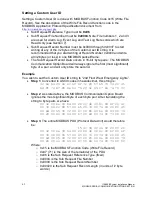
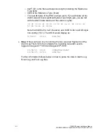
Page 63: ... You wish to set the Custom User ID string to 2nd Floor West Emergency Lights Step 1 Converted to ASCII codes in hexadecimal this string is 32 6e 64 20 46 6c 6f 6f 72 20 57 65 73 74 20 45 6d 65 72 67 65 6e 63 79 20 4c 69 67 68 74 73 00 Step 2 As stated above the MODBUS Communication Option Board ignores the most significant byte of each byte pair After translating the string to byte pairs we have ...

Page 64: ...on Option Board has conformity level 3 so it can support any Device ID code 1 basic device ID 2 regular device ID 3 extended device ID 4 specific device ID The MODBUS Communication Option Board supports Object IDs 0x00 Vendor Name through 0x06 UserApplicationName Object ID 0x06 UserApplicationName is used to return the Custom User ID string if set SECTION 7 Retrieving File Records Alarm Event and ...

Page 65: ...om the respective file in the second least significant byte of the pair All bytes from the files are going to be printable ASCII characters or tabs ASCII 0x09 or DOS style line endings ASCII 0x0D and ASCII 0x0A See the sections below to understand how to parse the data in the files Example In this example we will retrieve the contents of the Alarm Log file Step 1 The first step is to determine the...

Page 66: ...gnificant bytes of each byte pair you are left with the ASCII data read out of the Alarm Log file 31 39 2f 30 38 2f 32 31 09 30 39 3a 33 31 09 49 4e 56 45 52 54 45 52 20 46 41 55 4c 54 0D 0A 31 Note that 0x09 is the tab character and 0x0D 0x0A is a DOS style line ending r n The ASCII would display as 19 08 21 09 31 INVERTER FAULT 1 Request PDU 2 14 07 06 00 01 00 20 00 17 Where o 0x14 20 is the Re...

Page 67: ... of the Alarm Log file 39 2f 30 38 2f 32 35 09 32 32 3a 31 34 09 4c 4f 57 20 56 41 43 0D 0A Note that 0x09 is the tab character and 0x0D 0x0A is a DOS style line ending r n The ASCII would display as 9 08 25 22 14 LOW VAC Step 3 Now we have only to combine the two received fragments of the Alarm Log File to form the complete file revealing two alarm events logged on August 21st 2019 and August 25t...

Page 68: ...rm descriptor which describes the cause of the alarm Each line ends with a DOS style line ending r n Event Logs This is an example of an Event Log file 19 08 16 11 35 13 1 277 4 10 2 24 0 19 08 18 20 09 6 3 278 5 10 6 28 3 Each line in the file begins with a timestamp in the format YY MM DD HH MM Note that the time is in 24 hour format Note also that the time must be set up correctly in the invert...

Page 69: ...using the display mounted on the front of the cabinet A tab character separates the date from the time Tab characters separate all the fields in the file The next field describes whether the test was a monthly or yearly automatically scheduled test M for Monthly or Y for Yearly The next field describes the duration of the test in integer minutes The next field is a count for the number of faults e...

Page 70: ...CTION MODBUS TCP AND SNMP COMMUNICATION OPTION MANUAL SINGLE PHASE ILLUMINATOR SUPERNOVA EMERGENCY LIGHTING CENTRAL INVERTER Myers Emergency Power Systems 44 South Commerce Way Bethlehem PA 18017 1 800 526 5088 610 868 3500 Fax 610 868 8686 Service 610 868 5400 www myerseps com ...

Page 71: ...73 Description of Operation 73 SECTION 3 73 Default Ethernet Settings 73 Default MODBUS TCP Settings 73 Default SNMP Settings 73 SECTION 4 74 Object Summary 74 SECTION 5 76 Connecting to the BB2 6010 Web Server the First Time 76 Setting Up IP Address and LAN Settings 77 Setting Up MODBUS TCP 78 Setting Up the SNMP Agent 78 Setting Up SNMP Traps 78 Saving and Activating Your Changes 81 ...

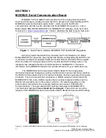
Page 72: ...t goes down and the inverter switches to battery power The integrator may integrate directly to the Ethernet link on the BB2 6010 The below information on the MODBUS Serial Communication Board is for your information only The MODBUS Serial Communication Option Board for the single phase Illuminator Supernova Emergency Lighting Central Inverter has two internal connections the RS232 communication b...

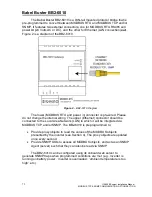
Page 73: ...ired Please do not change the internal wiring The upper Ethernet connector should be connected to the Local Area Network LAN to which it will be integrated via MODBUS TCP and or SNMP The BB2 6010 is preprogrammed to Provide proxy objects to read the values of the MODBUS objects presented by the inverter see Section 4 The proxy objects are updated once every second Provide SNMP OIDs to access all M...

Page 74: ...programmed to transmit SNMP traps when a programmed condition is met analog value goes above or below a threshold value or binary flag gets set to 1 or cleared to 0 The traps can be sent to specified IP addresses on the LAN SECTION 3 Default Ethernet Settings IP Address 10 0 0 101 static Subnet Mask 255 255 255 0 Gateway 10 0 0 1 DHCP Client Turned off by default but DHCP is supported Web Server P...

Page 75: ...3 6 1 4 1 3815 1 2 2 1 1 1 1 1 2 25 Battery Current 0 1 Amps DC e g 52 5 2A Binary Values status flags from the inverter value is either 0 or 1 100 0x0064 1 3 6 1 4 1 3815 1 2 2 1 1 1 1 1 2 101 System Ready Status 0 false or 1 true 101 0x0065 1 3 6 1 4 1 3815 1 2 2 1 1 1 1 1 2 102 AC Line Present Status 0 false or 1 true 102 0x0066 1 3 6 1 4 1 3815 1 2 2 1 1 1 1 1 2 103 Battery Charging Status 0 f...

Page 76: ...Units 143 0x008F 1 3 6 1 4 1 3815 1 2 2 1 1 1 1 1 2 144 Inverter Failure 0 false or 1 true 144 0x0090 1 3 6 1 4 1 3815 1 2 2 1 1 1 1 1 2 145 Near Low Battery 0 false or 1 true 145 0x0091 1 3 6 1 4 1 3815 1 2 2 1 1 1 1 1 2 146 In Load Reduction 0 false or 1 true 147 0x0093 1 3 6 1 4 1 3815 1 2 2 1 1 1 1 1 2 148 Inverter Runtime Failure 0 false or 1 true ...

Page 77: ...ng a command prompt with administrator privileges First type ipconfig and note the IPv4 address listed for the adapter that is connected to the same LAN as the BB2 6010 or directly to the BB2 6010 Now type the following command into the command prompt but replace the X X X X with your PC s IPv4 address route add 10 0 0 0 mask 255 255 255 0 X X X X You should now be able to view the BB2 6010 homepa...

Page 78: ...ur BB2 6010 to have and the Subnet Mask and Gateway address for the LAN that the BB2 6010 will be on If you wish the BB2 6010 to be a DHCP client i e to automatically be assigned IP address subnet mask and gateway address from a DHCP server if one exists and is reachable on the LAN simply enter 255 255 255 255 as the IP Address However DHCP is not recommended because it means the IP address of the...

Page 79: ...stem Setup Setup Network Make the required changes click the Set Ports button and then refer to the Saving and Activating Your Changes subsection below to make your changes permanent otherwise they may be lost if the inverter loses power for long enough for the entire battery to deplete or if maintenance is performed on the inverter Setting Up the SNMP Agent Once the IP address is correctly set th...

Page 80: ...eater than click the this value radio button if it is not already selected and enter 300 as the value 300 is 30 0 C in units of 0 1 C as described in Section 4 4 For analog values such as ambient temperature consider setting a hysteresis For our example you might want to put in a hysteresis of 2 C 20 in units of 0 1 C so that if the temperature is right on the 30 C mark and oscillating with small ...

Page 81: ...ox if using hostnames please ensure that DNS server has been correctly set in the Setting Up IP Address and LAN Settings section above Optionally enter a textual name for the device such as Maintenance PC or Net Mgmt Server etc Check the Group 1 checkbox Click the Update button Next go to the IP Network SNMP Setup Trap Enable webpage and click the Trap on True checkbox and the Enable Group 1 check...

Page 82: ...s other than changing IP address are temporary They will not take effect until you activate them plus they will be lost on a power cycle of the BB2 6010 until you permanently save them To permanently save your programming go to System Setup Config File select InverterModbus xml from the dropdown list if it is not already selected and click the Save button The BB2 6010 will take 10 seconds or so to...

Page 83: ...82 115895B System Installation Manual SERIAL TO ETHERNET ADAPTER OPTION SECTION RS 232 Communications Illuminator Supernova Users Manual ...

Page 84: ...mand 85 Help screen 86 Version 86 Alarm Setpoint 86 Meter Functions 87 Status 87 Alarms 88 Alarms Events and Tests Dump 88 Date and Time 91 LOCATION OF THE RS232 PORT FOR E IE 6 16 7k 92 LOCATION OF THE RS232 PORT FOR E IE 1 5 5 0k 92 LOCATION OF THE RS232 PORT FOR EM 1 0 2 8k 93 The ZOOM Modem Optional 96 Configuring the ZOOM Modem optional 96 Dialing the ZOOM Modem 96 ...

Page 85: ...g Central Inverters CONNECTION The Central Inverter has a 9 pin Sub D DB9 female connector typically located on the back inside of the front display panel located on the door of the inverter See below for the exact location of the connector The connection between the Client and the Inverter is a straight through connection Do not use a Null Modem Cable that flips pins 2 and 3 Pin 2 and Pin 3 are t...

Page 86: ...arriage returns When the inverter is not in shell mode it will not echo back characters you type even though it is indeed receiving them To see what you are typing when the inverter is not in shell mode turn on the local echo setting on your terminal emulator When the inverter is in shell mode it will echo back characters you type You will want to turn off the local echo setting on your terminal e...

Page 87: ...mmand CMD ver IF 2 08 FP 1 02 CMD Alarm Setpoint When the set point command is entered the following data is displayed CMD setpoint lvac 108 0 off hvac 132 0 off nlbatt 111 0 off lbatt 105 0 off htemp 45 0 on lrc 0 0 off lvac is the Low Voltage AC alarm hvac is the High Voltage AC alarm nlbatt is the Near Low Battery Voltage alarm lbatt is the Low Battery Voltage Alarm htemp is the High temperatur...

Page 88: ...emperature inside the inverter cabinet in degrees Celsius To convert to degrees Fahrenheit subtract 32 then multiply by 5 then divide by 9 imin is the cumulative number of minutes over its lifetime that the inverter has spent running on battery power days is the number of days that the inverter system has been running vaout is the output power of the inverter in Vars VA voltage ampere reactive iwa...

Page 89: ...he High Ambient alarm indicates excessively high temperature inside the inverter cabinet The High VAC alarm indicates an excessively high input voltage utility to the inverter The Low VAC alarm indicates an excessively low input voltage utility to the inverter The Low Battery alarm indicates that the battery charge has almost been depleted The Near Low Battery alarm indicates that the inverter is ...

Page 90: ...75 UTILITY 09 20 19 17 49 END 09 20 19 17 49 2 75 UTILITY 02 11 19 12 52 END 02 11 19 12 52 3 75 UTILITY 11 29 18 13 36 END 11 29 18 13 36 4 75 UTILITY 09 11 18 12 41 END 09 11 18 12 54 74 75 LOAD REDUCTION 07 25 16 13 58 END 07 25 16 13 58 75 75 LOAD REDUCTION 07 25 16 13 58 END 07 25 16 13 58 CMD The alarm log has up to 75 entries and in this example it is full The alarms shown above include UTI...

Page 91: ...to be replaced Again there is space for up to 75 logs The first line of a log entry will indicate whether the self test was an automated monthly self test MONTHLY or an automated yearly self test YEARLY The rest of the entry will tell you the timestamp of the self test the duration of the test in minutes whether or not faults were detected the output voltage in Volts and current in Amps of the inv...

Page 92: ...ange a parameter type the dt command then press the tab key then type the parameter number press tab again then type the new value you wish to set the parameter to and finally press enter Note The inverter does not support Daylight Savings Time If you set the inverter date and time during daylight savings note that logged timestamps during non daylight saving times i e winter will be one hour ahea...

Page 93: ...92 115895B System Installation Manual SERIAL TO ETHERNET ADAPTER OPTION SECTION LOCATION OF THE RS232 PORT FOR I 1 75 5 0K LOCATION OF THE RS232 PORT FOR I 6 25 7 5K ...

Page 94: ...93 115895B System Installation Manual SERIAL TO ETHERNET ADAPTER OPTION SECTION LOCATION OF THE RS232 PORT FOR I 10 0 16 7K ...

Page 95: ...94 115895B System Installation Manual SERIAL TO ETHERNET ADAPTER OPTION SECTION ...

Page 96: ...95 115895B System Installation Manual SERIAL TO ETHERNET ADAPTER OPTION SECTION ...

Page 97: ...l Make sure there is communication by typing AT enter until the message OK appears Type the following AT commands ATM1 enter speaker on until connected AT D0 enter ignore DTR AT K0 enter no flow control ATS0 1 enter auto answer after one ring AT W0 store to non volatile memory Dialing the ZOOM Modem Type AT enter until the message OK appears Type for example ATD9 16109545224 enter ATD is the comma...

Page 98: ...ERIAL TO ETHERNET ADAPTER OPTION SECTION Serial to Ethernet Adapter Quick Start Manual Myers Emergency Power Systems 44 South Commerce Way Bethlehem PA 18017 1 800 526 5088 610 868 3500 Fax 610 868 8686 Service 610 868 5400 www myerseps com ...

Page 99: ...om SSH to Telnet 5 Factory Reset For more information on instead using the Virtual Com Port feature or other features please reference the IOLAN Secure User s Guide Perle Document Part Number 5500431 10 currently hosted at the following URL https www perle com support_services documentation_pdfs iolan_scg sdg stg_ug pdf 1 Basic Network Configuration for your LAN The default static IP address of th...

Page 100: ...P address is highly recommended even if your LAN includes a DHCP dynamic IP server because with DHCP your IOLAN SDG1 might periodically change IP address 9 Click the Apply button 10 Click the Reboot IOLAN button that just appeared in the bottom right 11 Close your web browser window 12 Disconnect the Ethernet cable between your PC and the IOLAN SDG1 13 Restore the previous IP settings for the wire...

Page 101: ...ers EPS RS 232 Communication Protocol as described in the RS 232 Protocol Manual To find the right RS 232 Protocol Manual in PDF format For Series E or Series IE inverters Google Myers EPS 114063 pdf For Series CI Series CIII Series CR Series DR or Series SR inverters Google Myers EPS 113786 pdf 3 Changing the Port Number Depending on your organization s IT policies sometimes certain port numbers ...

Page 102: ...the Changing the Port Number section above section 3 except in step 6 instead of changing the port number change the selected protocol from SSH to Telnet 5 Factory Reset If the configuration or operation of your IOLAN SDG1 were to somehow get corrupted beyond recovery or were you to forget or lose the IP address of your IOLAN SDG it can be simply recovered using the Reset pinhole button next to th...

Page 103: ...Y SYSTEM OPTION SECTION BATTERY THERMAL RUNAWAY SYSTEM OPTION MANUAL FOR EMERGENCY LIGHTING CENTRAL INVERTER Myers Emergency Power Systems 44 South Commerce Way Bethlehem PA 18017 1 800 526 5088 610 868 3500 Fax 610 868 8686 Service 610 868 5400 www myerseps com ...

Page 104: ...ION SECTION Table of Contents SECTION 1 104 System Description 104 Power Supply Summary Relay PCB connections 104 Temperature Sensor PCB Connections 105 System Schematic 106 SECTION 2 106 Description of Operation 106 LED Definitions 107 SECTION 3 108 System Installation 108 ...

Page 105: ...he temperature sensor PCB is shown in Picture 2 Power Supply Summary Relay PCB connections The Power Supply and Summary Alarm PCB can be identified by the assembly number PCB404394XXX The main power is supplied to the connector on the left If jumpers R4 and R5 are installed the input voltage required is 115vac If jumper R3 is installed then the input voltage is set up to accept a 230vac input Conn...

Page 106: ...circuit board to another Note A maximum of four daisy chained Temperature Sensor PCB s can be connected to a single Power Supply Summary Relay PCB Two position insulation displacement connectors J1 J5 provide the termination for the battery temperature probes The temperature probe are NTC type and have a measurement range from 40 C to 125 C The wire length of the temperature probes can be cut to a...

Page 107: ...tion The Thermal Runaway System monitors each of the battery temperatures individually and annunciates an alarm if one of two conditions occurs 1 If any of the connected battery temperature probes measure a differential rise greater than 40 C between the measured battery temperature and the ambient temperature as measured from a temperature sensor on the Temperature Sensor PCB Note The Temperature...

Page 108: ... Overtemp LED on the power supply summary relay pcb will be illuminated LED Definitions 1 Power Supply Summary Relay PCB PCB404394XXX a Battery Overtemp LED Illuminated when a battery is experiencing thermal runaway condition on one or more of the batteries on the connected Temperature Sensor PCB 2 Temperature Sensor PCB PCB404391XXX a PWR LED Illuminated when the 5V supply is present on the tempe...

Page 109: ...ill be a normally open common and normally closed set of contacts rated for 277VAC 0 5AAC b The power and error signal connections will need to be wired from the Power Supply Summary Relay PCB to the first Temperature Sensor PCB via the wire supplied in the kit To install the wires in the power supply summary relay pcb follow the instructions below i Strip about off from the end of each of the thr...

Page 110: ...awing specific to the Emergency Lighting Inverter System Installed Note Do not connect more than four temperature sensor pcb s to one power supply summary relay pcb and do not connect power supply summary relay pcb s to each other a The power and error signal connections will need to be wired from the Power Supply Summary Relay PCB to the first Temperature Sensor PCB via the wire supplied in the k...

Page 111: ...oved and ends of the temperature probe are full insulated and separated by at least 1 inch See Picture 5 Picture 5 ii Lift the top of the connector fully and insert the probe wire all the way into the connector The wire should insert about inside the connector See Picture 6 Note The blade of the insulation displacement knife is in the back of the left side hole and if the top is not fully lifted t...

Page 112: ...tem Installation Manual BATTERY THERMAL RUNAWAY SYSTEM OPTION SECTION Figure 2 Stripped Probe leads insert into connectors Use supplied Velcro in kit and attach it to the plastic box See diagram for location placement ...

Page 113: ...112 115895B System Installation Manual DRAWINGS SECTION PART III DRAWINGS Drawings section continues on next page ...

Page 114: ...113 115895B System Installation Manual DRAWINGS SECTION ...

Page 115: ...114 115895B System Installation Manual DRAWINGS SECTION ...

Page 116: ...115 115895B System Installation Manual DRAWINGS SECTION ...

Page 117: ...116 115895B System Installation Manual DRAWINGS SECTION ...

Page 118: ...117 115895B System Installation Manual DRAWINGS SECTION ...

Page 119: ...118 115895B System Installation Manual DRAWINGS SECTION ...

Page 120: ...119 115895B System Installation Manual DRAWINGS SECTION ...

Page 121: ...120 115895B System Installation Manual DRAWINGS SECTION ...

Page 122: ...121 115895B System Installation Manual DRAWINGS SECTION ...

Page 123: ...122 115895B System Installation Manual DRAWINGS SECTION ...

Page 124: ...123 115895B System Installation Manual DRAWINGS SECTION ...

Page 125: ...124 115895B System Installation Manual DRAWINGS SECTION ...

Page 126: ...125 115895B System Installation Manual DRAWINGS SECTION ...

Page 127: ...126 115895B System Installation Manual DRAWINGS SECTION ...

Page 128: ...127 115895B System Installation Manual DRAWINGS SECTION ...

Page 129: ...128 115895B System Installation Manual DRAWINGS SECTION ...

Page 130: ...129 115895B System Installation Manual DRAWINGS SECTION ...

Page 131: ...130 115895B System Installation Manual Notes ...

Reviews: