65
115895B System Installation Manual
MODBUS SERIAL COMMUNICATION OPTION SECTION
o
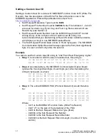
0x0001 is the File Number (for the Alarm Log File)
o
0x0000 is the Record Number (we
’re starting to read the file from
byte 0)
o
0x0020 (32) is the Record Length. We wish to read the first 32
bytes of the file.
Response PDU 1
14 42 41 06
00 31 00 39 00 2f 00 30 00 38 00 2f 00 32 00 31
00 09 00 30 00 39 00 3a 00 33 00 31 00 09 00 49
00 4e 00 56 00 45 00 52 00 54 00 45 00 52 00 20
00 46 00 41 00 55 00 4c 00 54 00 0D 00 0A 00 31
Where:
o
0x14 (20) is the Read File Record function code
o
0x42 (66) is the remaining length of the PDU in bytes
o
0x41 (65) is the file read response length (including the Reference
Type byte)
o
0x06 is the Reference Type (fixed)
o
The last 64 bytes of the PDU are byte pairs. If you eliminate all the
(0x00 valued) most significant bytes of each byte pair, you are left
with the ASCII data read out of the Alarm Log file:
31 39 2f 30 38 2f 32 31 09 30 39 3a 33 31 09 49
4e 56 45 52 54 45 52 20 46 41 55 4c 54 0D 0A 31
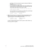
Note that 0x09 is the
‘tab’ character, and 0x0D 0x0A is a DOS style
line ending (
“\r\n”). The ASCII would display as:
19/08/21 09:31
INVERTER FAULT
1
Request PDU 2
14 07 06 00 01 00 20 00 17
Where:
o
0x14 (20) is the Read File Record function code
o
0x07 is the remaining length of the PDU in bytes
o
0x06 is the Reference Type (fixed)
o
0x0001 is the File Number (for the Alarm Log File)
o
0x0020 (32) is the Record Number (we
’re starting to read the file
from byte 32, where we left off)
o
0x0017 (23) is the Record Length. This is the remainder of the file
(55
– 32 = 23 bytes)
Response PDU 2
14 30 2F 06
00 39 00 2f 00 30 00 38 00 2f 00 32 00 35 00 09
00 32 00 32 00 3a 00 31 00 34 00 09 00 4c 00 4f
00 57 00 20 00 56 00 41 00 43 00 0D 00 0A
Where:
o
0x14 (20) is the Read File Record function code
o
0x30 (48) is the remaining length of the PDU in bytes
Summary of Contents for Illuminator Supernova Series
Page 16: ...15 115895B System Installation Manual Figure 5 2 AC Connections for 6 25 k W 7 5 kW systems ...
Page 17: ...16 115895B System Installation Manual Figure 5 3 AC Connections for 10 kW 16 7 kW systems ...
Page 30: ...115895B System Installation Manual PART II OPTIONS MANUALS Section continues on next page ...
Page 95: ...94 115895B System Installation Manual SERIAL TO ETHERNET ADAPTER OPTION SECTION ...
Page 96: ...95 115895B System Installation Manual SERIAL TO ETHERNET ADAPTER OPTION SECTION ...
Page 114: ...113 115895B System Installation Manual DRAWINGS SECTION ...
Page 115: ...114 115895B System Installation Manual DRAWINGS SECTION ...
Page 116: ...115 115895B System Installation Manual DRAWINGS SECTION ...
Page 117: ...116 115895B System Installation Manual DRAWINGS SECTION ...
Page 118: ...117 115895B System Installation Manual DRAWINGS SECTION ...
Page 119: ...118 115895B System Installation Manual DRAWINGS SECTION ...
Page 120: ...119 115895B System Installation Manual DRAWINGS SECTION ...
Page 121: ...120 115895B System Installation Manual DRAWINGS SECTION ...
Page 122: ...121 115895B System Installation Manual DRAWINGS SECTION ...
Page 123: ...122 115895B System Installation Manual DRAWINGS SECTION ...
Page 124: ...123 115895B System Installation Manual DRAWINGS SECTION ...
Page 125: ...124 115895B System Installation Manual DRAWINGS SECTION ...
Page 126: ...125 115895B System Installation Manual DRAWINGS SECTION ...
Page 127: ...126 115895B System Installation Manual DRAWINGS SECTION ...
Page 128: ...127 115895B System Installation Manual DRAWINGS SECTION ...
Page 129: ...128 115895B System Installation Manual DRAWINGS SECTION ...
Page 130: ...129 115895B System Installation Manual DRAWINGS SECTION ...
Page 131: ...130 115895B System Installation Manual Notes ...


