


89
115895B System Installation Manual
SERIAL TO ETHERNET ADAPTER OPTION SECTION
The dump command must be followed by a tab and then either
“alarms”, “tests” or “events” as the
second field.
After pressing the ‘enter’ key, the inverter will display a “Press Enter when ready…”
prompt. Press the ‘enter’ key once again, and the inverter will dump out the specified log. Note
that this log may be several kilobytes in size and will be streamed out in one go.
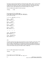
Here is an abbreviated example of an alarm log dump:
CMD>dump alarms
Final settings will be displayed next.
If you wish to save to a file, enable text capture now.
Do not forget to stop capture after data is transferred.
Press Enter when ready...
***********< ALARM LOGS >***********
1/75 UTILITY
09/20/19 17:49
END : 09/20/19 17:49
2/75 UTILITY
02/11/19 12:52
END : 02/11/19 12:52
3/75 UTILITY
11/29/18 13:36
END : 11/29/18 13:36
4/75 UTILITY
09/11/18 12:41
END : 09/11/18 12:54
: : : :
74/75 LOAD REDUCTION
07/25/16 13:58
END : 07/25/16 13:58
75/75 LOAD REDUCTION
07/25/16 13:58
END : 07/25/16 13:58
CMD>
The alarm log has up to 75 entries, and in this example, it is full. The alarms shown above include
UTILITY alarms and LOAD REDUCTION alarms (see the write-
up of the ‘alarms’ command
above for details on what these mean). The first date and time is the timestamp of the start of the
alarm event (when the alarm condition asserted), and the second date and time is the timestamp
of the end of the alarm event (when the alarm condition unasserted).
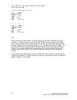
Here is an abbreviated example of a test log dump:
CMD>dump tests
Final settings will be displayed next.
If you wish to save to a file, enable text capture now.
Summary of Contents for Illuminator Supernova Series
Page 16: ...15 115895B System Installation Manual Figure 5 2 AC Connections for 6 25 k W 7 5 kW systems ...
Page 17: ...16 115895B System Installation Manual Figure 5 3 AC Connections for 10 kW 16 7 kW systems ...
Page 30: ...115895B System Installation Manual PART II OPTIONS MANUALS Section continues on next page ...
Page 95: ...94 115895B System Installation Manual SERIAL TO ETHERNET ADAPTER OPTION SECTION ...
Page 96: ...95 115895B System Installation Manual SERIAL TO ETHERNET ADAPTER OPTION SECTION ...
Page 114: ...113 115895B System Installation Manual DRAWINGS SECTION ...
Page 115: ...114 115895B System Installation Manual DRAWINGS SECTION ...
Page 116: ...115 115895B System Installation Manual DRAWINGS SECTION ...
Page 117: ...116 115895B System Installation Manual DRAWINGS SECTION ...
Page 118: ...117 115895B System Installation Manual DRAWINGS SECTION ...
Page 119: ...118 115895B System Installation Manual DRAWINGS SECTION ...
Page 120: ...119 115895B System Installation Manual DRAWINGS SECTION ...
Page 121: ...120 115895B System Installation Manual DRAWINGS SECTION ...
Page 122: ...121 115895B System Installation Manual DRAWINGS SECTION ...
Page 123: ...122 115895B System Installation Manual DRAWINGS SECTION ...
Page 124: ...123 115895B System Installation Manual DRAWINGS SECTION ...
Page 125: ...124 115895B System Installation Manual DRAWINGS SECTION ...
Page 126: ...125 115895B System Installation Manual DRAWINGS SECTION ...
Page 127: ...126 115895B System Installation Manual DRAWINGS SECTION ...
Page 128: ...127 115895B System Installation Manual DRAWINGS SECTION ...
Page 129: ...128 115895B System Installation Manual DRAWINGS SECTION ...
Page 130: ...129 115895B System Installation Manual DRAWINGS SECTION ...
Page 131: ...130 115895B System Installation Manual Notes ...


