


21
115895B System Installation Manual
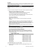
NOTE: For standard 90-minute runtimes, 1.75 kW, 2.5 kW, 3.75 kW, 5.0 kW, 6.25 kW,
7.5 kW, 10.0kW, 12.5kW, and 16.7kW models have one battery string.
2.
Clean the cable connectors with the wire brush before you make the battery
connections.
NOTE As you carry out the following step, use these guidelines:
If you are using conductive grease, apply a thin coating of high-temperature
conductive grease on each post and every cable connector before you assemble
and torque the connection to slow corrosion.
If you use nonconductive grease like petroleum jelly, do not apply any grease
before you make the connections and torque them. Instead, make the connection
first; then, torque it to the value shown in Table 6.1. After you make the connection,
apply a coating of the nonconductive grease to the hardware at the battery
terminals.
3.
In each battery string, connect the battery tie straps between the batteries as
shown in the battery-wiring diagram (positive terminal to negative terminal).
Torque the connections to the value shown for your battery in Table 6.1.
1.
Connect the battery cables from one shelf to the next as shown on the battery-
wiring diagram. Torque the connections to the value shown for your battery in
Table 6.1.
2.
Connect the red wire from the battery circuit breaker to the positive of the battery
as shown on the battery-wiring diagram.
CAUTION
Hazardous voltage is present! System batteries are high current sources. These
batteries can produce dangerous voltages, extremely high currents, and a risk of
electric shock.
6.
Next, use the voltmeter to check the DC voltage between the positive (+)
position on the battery block inside the electronics cabinet and the unconnected
battery negative terminal. This voltage should be approximately the battery
voltage record on the unit ID label. If it is greater than + or
– 5% Vdc, review the
battery wiring diagram. Correct any wiring errors and recheck the DC voltage; do
not go on until your measurement is or
– 5% Vdc. If the measurement is
too high and you cannot find the cause of the problem, call SERVICE.
CAUTION
If you do not verify that voltage and current direction are correct, the equipment may
fail.
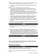
Connecting the Negative Battery Cable(s) to the Battery String(s)
Connect the cable to the battery (-) negative.
Replacing the Batteries
CAUTION
A battery can present a risk of electrical shock and high short circuit current. A qualified
electrician familiar with battery systems should service the batteries.
Review all the safety instructions at the beginning of this chapter before you replace any
batteries.
Summary of Contents for Illuminator Supernova Series
Page 16: ...15 115895B System Installation Manual Figure 5 2 AC Connections for 6 25 k W 7 5 kW systems ...
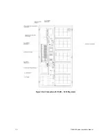
Page 17: ...16 115895B System Installation Manual Figure 5 3 AC Connections for 10 kW 16 7 kW systems ...
Page 30: ...115895B System Installation Manual PART II OPTIONS MANUALS Section continues on next page ...
Page 95: ...94 115895B System Installation Manual SERIAL TO ETHERNET ADAPTER OPTION SECTION ...
Page 96: ...95 115895B System Installation Manual SERIAL TO ETHERNET ADAPTER OPTION SECTION ...
Page 114: ...113 115895B System Installation Manual DRAWINGS SECTION ...
Page 115: ...114 115895B System Installation Manual DRAWINGS SECTION ...
Page 116: ...115 115895B System Installation Manual DRAWINGS SECTION ...
Page 117: ...116 115895B System Installation Manual DRAWINGS SECTION ...
Page 118: ...117 115895B System Installation Manual DRAWINGS SECTION ...
Page 119: ...118 115895B System Installation Manual DRAWINGS SECTION ...
Page 120: ...119 115895B System Installation Manual DRAWINGS SECTION ...
Page 121: ...120 115895B System Installation Manual DRAWINGS SECTION ...
Page 122: ...121 115895B System Installation Manual DRAWINGS SECTION ...
Page 123: ...122 115895B System Installation Manual DRAWINGS SECTION ...
Page 124: ...123 115895B System Installation Manual DRAWINGS SECTION ...
Page 125: ...124 115895B System Installation Manual DRAWINGS SECTION ...
Page 126: ...125 115895B System Installation Manual DRAWINGS SECTION ...
Page 127: ...126 115895B System Installation Manual DRAWINGS SECTION ...
Page 128: ...127 115895B System Installation Manual DRAWINGS SECTION ...
Page 129: ...128 115895B System Installation Manual DRAWINGS SECTION ...
Page 130: ...129 115895B System Installation Manual DRAWINGS SECTION ...
Page 131: ...130 115895B System Installation Manual Notes ...


